

Translating lens holder assemblies employing bore relief zones, and optical connectors incorporating the same
a technology of bore relief zone and optical connector, which is applied in the direction of mountings, instruments, optics, etc., can solve the problems of limited design of conventional telecommunication cable assembly designs, time-consuming manufacturing process, high precision polishing cost and difficulty, etc., to facilitate optical connections and avoid or reduce coupling loss of signals
- Summary
- Abstract
- Description
- Claims
- Application Information
AI Technical Summary
Benefits of technology
Problems solved by technology
Method used
Image

Examples
Embodiment Construction
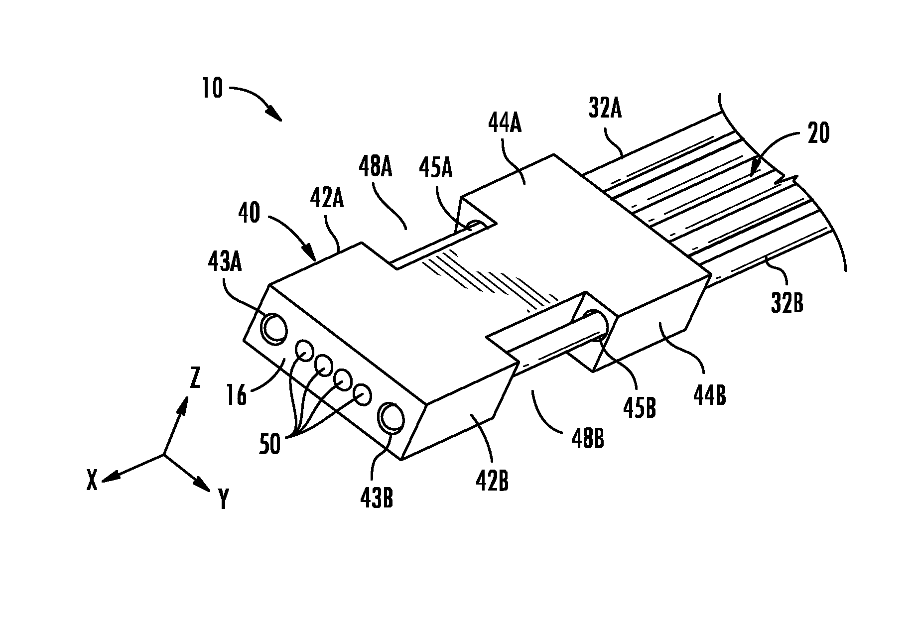
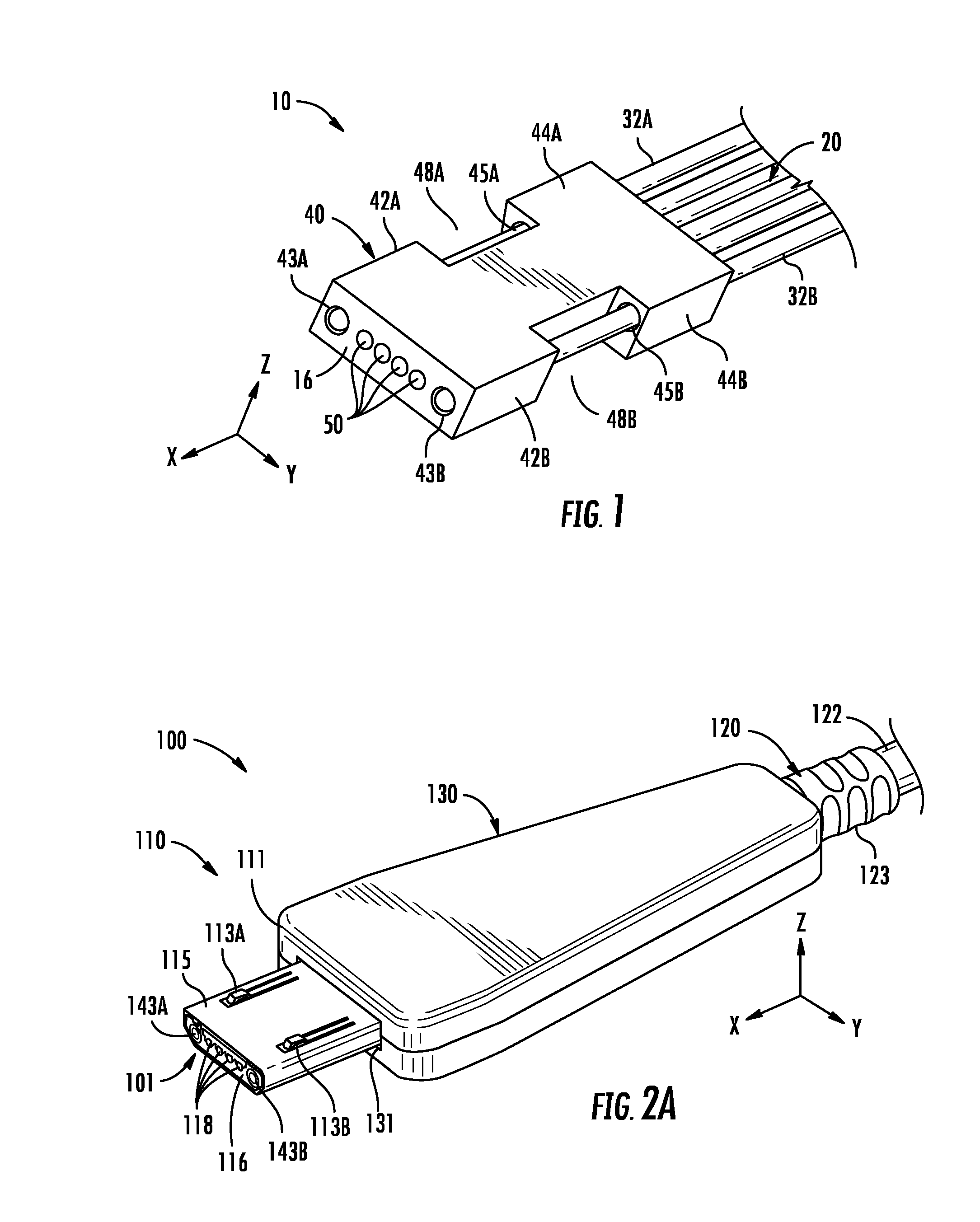
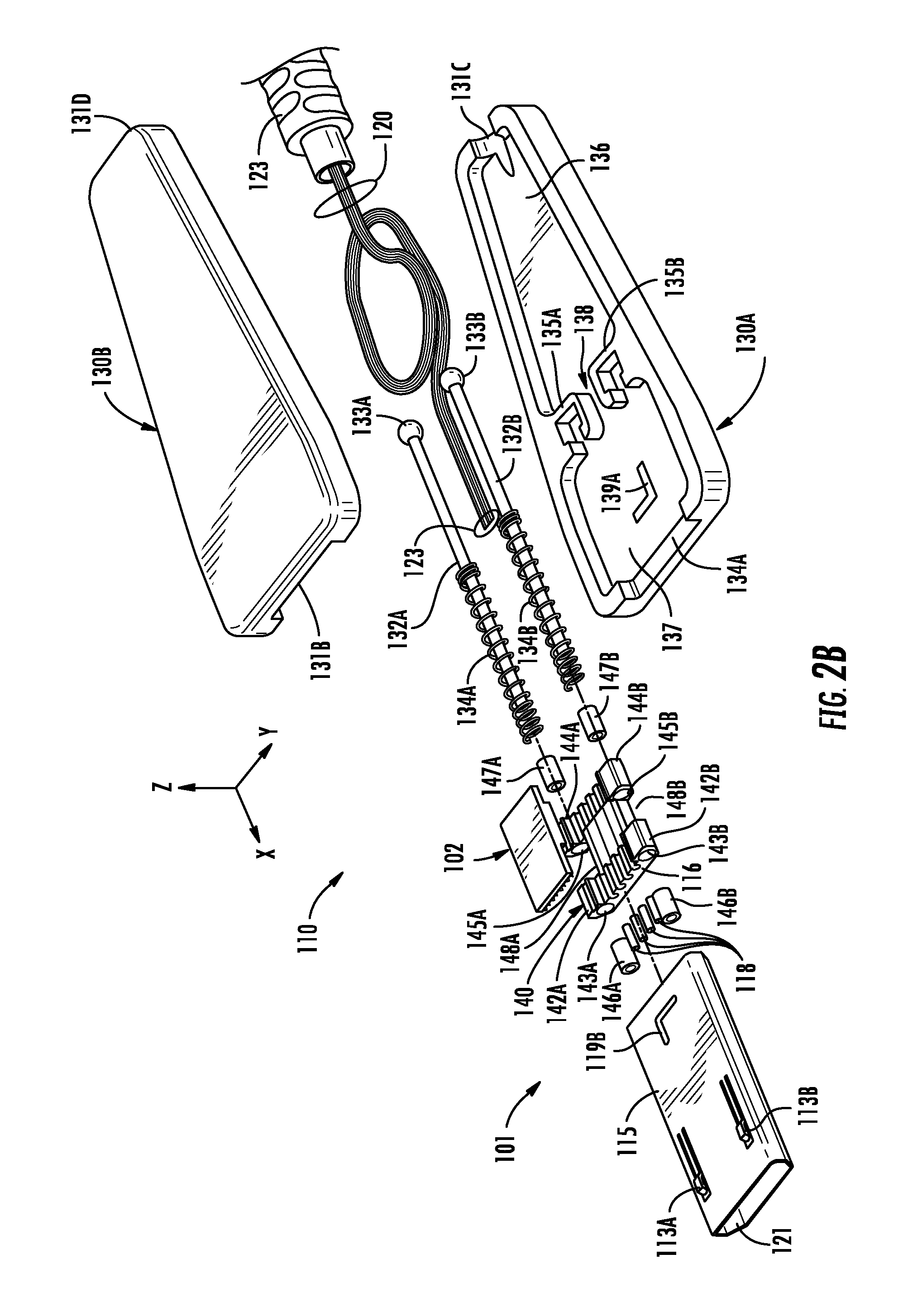
[0007]Fiber optic connectors having lens holders are disclosed to facilitate optical connections for the transfer of light signals between devices. For example, optical fibers can be optically connected to another optical device, such as a light-emitting diode (LED), laser diode, or opto-electronic device, for light / signal transfer. As another example, optical fibers can be optically connected to other optical fibers through mated fiber optic connectors as desired. In any of these cases, it is important that the end face of an optically connected optical fiber be precisely aligned with the optical device or other optical fiber to avoid or reduce coupling loss of the signal. For example, the optical fiber is disposed through a portion of a lens holder body that precisely locates the optical fiber with relation to the fiber optic lens.
[0008]Gradient index (GRIN) lenses offer an alternative to precision polishing used in telecommunication based connectors that have optical fiber-to-opt...
PUM
| Property | Measurement | Unit |
|---|---|---|
| outer diameter | aaaaa | aaaaa |
| outer diameter | aaaaa | aaaaa |
| diameter | aaaaa | aaaaa |
Abstract
Description
Claims
Application Information