
Method and Apparatus for Dielectric Barrier Discharge Wand Cold Plasma Device

a dielectric barrier and discharge wand technology, applied in the field of devices and methods for cold plasma generation, can solve the problems of increasing the generation of electrodes, limited use of floating electrode strategies, and thermal destruction of sensitive substrates such as skin

Inactive Publication Date: 2014-07-03
COLD PLASMA MEDICAL TECH
View PDF5 Cites 16 Cited by
  • Summary
  • Abstract
  • Description
  • Claims
  • Application Information

AI Technical Summary

Benefits of technology

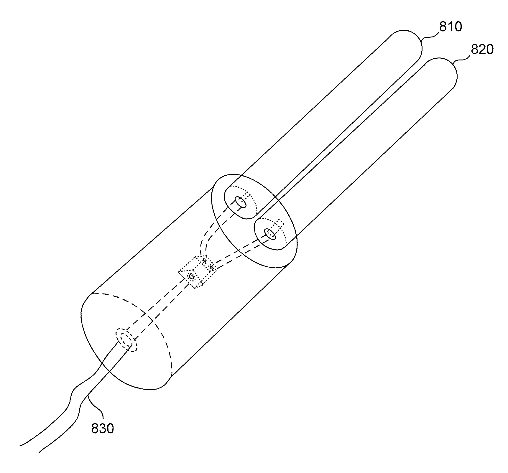
The invention is a device called a cold plasma dielectric barrier discharge (DBD) that is shaped like a wand and can be used to treat surfaces. The device has a rounded tip and a flat surface that is positioned far from the target surface. It can be made in different sizes depending on the treatment needs. The device generates non-thermal plasma that is effective in surface modification and pathogen destruction. It maintains an optimal treatment distance of 2 mm or less. The device is powered by a special multi-frequency harmonic-rich power supply. The device's rounded tip design allows for better treatment of complex biological and wound architecture. The device is designed to minimize contamination and surface irritation as no part of it comes into direct contact with the treatment surface.

Problems solved by technology

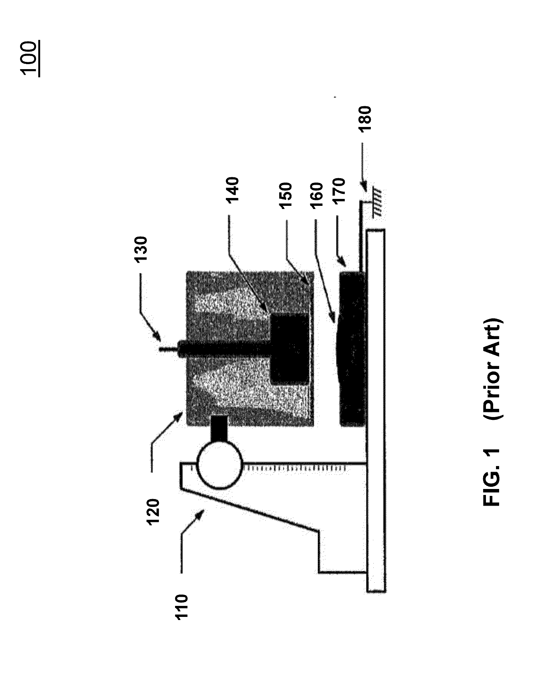
However, all conventional non-thermal DBD devices that utilize this floating electrode strategy are limited by the size of the area they can treat and the limited amount of variance allowed to the target treatment distance, generally less than 2 mm distance.
When attempts are made to increase the size of the electrode, and thereby the surface area of treatment, or increase the distance from the target that an arc can be initiated, the heat generated by the electrode increases and can cause thermal destruction of sensitive substrates such as skin.
All common single frequency cold plasma power supplies are limited in the amount of energy they can deliver to a target before thermal effects are initiated.
As a result, all electrodes connected to these power supplies are limited in their relative design size and consequently the surface area that they can effectively treat.
When placed too close to the treatment target (<1 mm), the desired reactive species and ions are not adequately delivered to the substrate and when placed too far, no plasma is initiated.
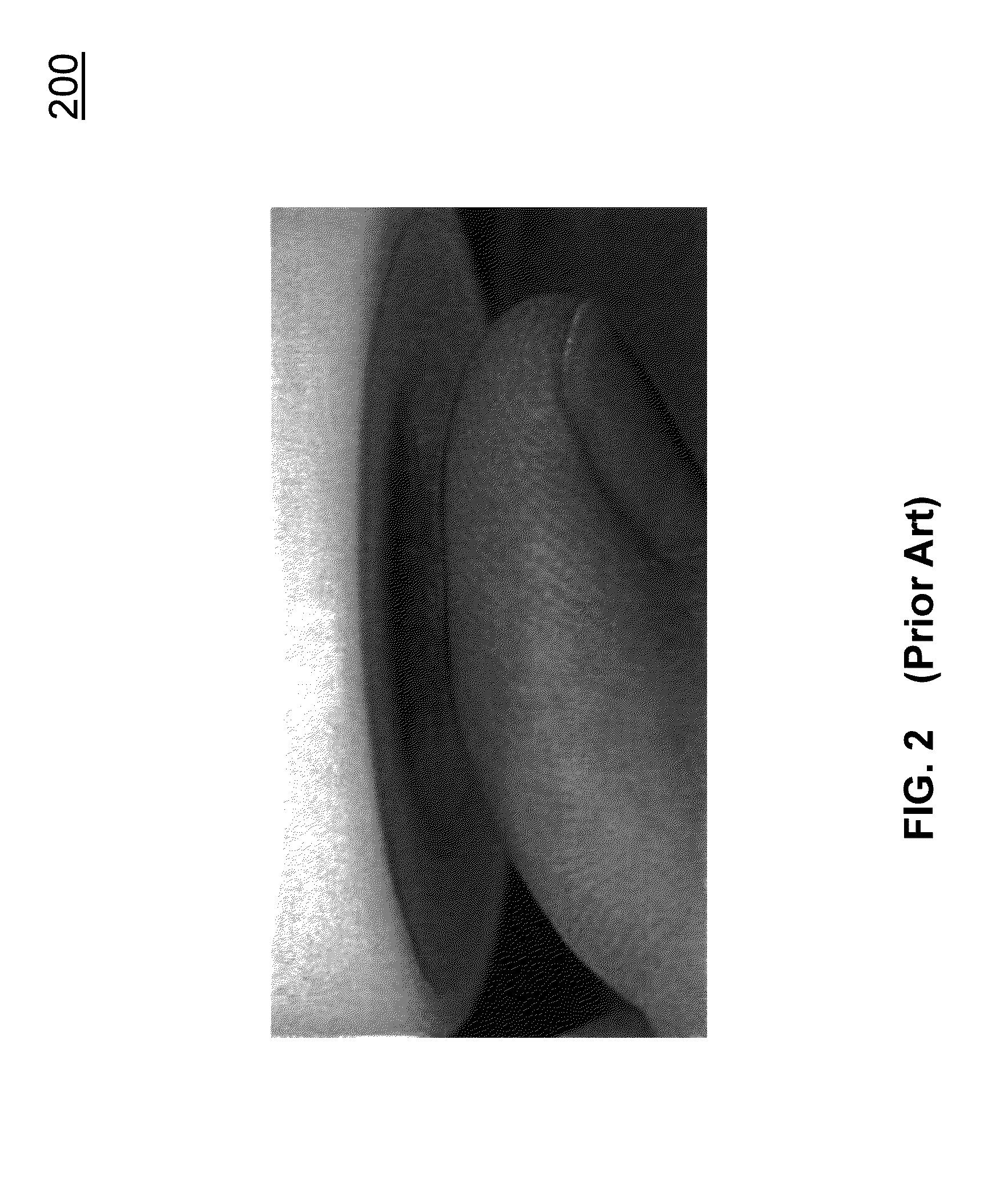
Existing DBD devices of this type have a flat planar structure (FIG. 2) and therefore maintaining an accurate degree of distance control is a significant challenge.
An additional confounding factor to controlling the distance between these devices and the wound is the potentially varying wound bed that also alters the distance between the plasma-generating device and the patient.
However, they cannot adjust to complex wound bed architecture and cannot be moved across a surface to facilitate larger treatment areas.
This design can follow the general contours of the treatment surface, however the wheels could potentially contact open wound areas.
In addition, this type of DBD device does not allow for the continuous micro-adjustments that would be necessary during an actual treatment session on a living patient having a complex biological and wound architecture.

Method used


Image

  • Method and Apparatus for Dielectric Barrier Discharge Wand Cold Plasma Device
  • Method and Apparatus for Dielectric Barrier Discharge Wand Cold Plasma Device
  • Method and Apparatus for Dielectric Barrier Discharge Wand Cold Plasma Device

Examples


Embodiment Construction

[0026]Cold temperature plasmas have attracted a great deal of enthusiasm and interest by virtue of their provision of plasmas at relatively low gas temperatures. The provision of plasmas at such a temperature is of interest to a variety of applications, including wound healing, anti-bacterial processes, treatments of musculoskeletal disorders, autoimmune disorder treatments and various other medical therapies and sterilization.

[0027]Embodiments of the present disclosure include cylindrical cold plasma DBD wand-like devices that provide a large cold plasma treatment area without the use of additional spatial control techniques. Powering these cylindrical cold plasma DBD devices with a multi-frequency harmonic-rich cold plasma (MFHCP) power supply avoids the formation of multiple discrete discharge points along the electrode (and associated pin-point heating and burning). The use of a MFHCP power supply results in a larger cold plasma treatment area (measured in centimeters or more) t...


PUM


Abstract

A cold plasma device having a broad surface of plasma generation allowing for the efficient treatment of larger areas with the benefit of being durable, portable and able to treat almost any anatomical structure. The cold plasma device has a constant radius surface, which creates a tangential surface with an infinite number of distances between the surface edge of the substrate under treatment and the device.

Description

CROSS REFERENCE TO RELATED APPLICATIONS[0001]This application claims the benefit of U.S. Provisional Application No. 61 / 747,828, filed Dec. 31, 2012 and entitled “Method and Apparatus for Dielectric Barrier Discharge Wand Cold Plasma Device,” which is incorporated herein by reference in its entirety.[0002]This application is related to U.S. Provisional Application No. 60 / 913,369, filed Apr. 23, 2007; U.S. patent application Ser. No. 12 / 038,159, filed Feb. 27, 2008 (which issued as U.S. Pat. No. 7,633,231); U.S. patent application Ser. No. 13 / 620,118, filed Sep. 14, 2012, and U.S. patent application Ser. No. 14 / 103,540, filed Dec. 11, 2013, each of which are herein incorporated by reference in their entireties.BACKGROUND[0003]1. Field of the Art[0004]The present invention relates to devices and methods for cold plasma generation, and, more particularly, to such devices that are formed in the shape of a wand and methods for using same.[0005]2. Background Art[0006]At present, non-therm...

Claims


Application Information

Patent Timeline
IPC IPC(8): A61B18/04
CPCA61B18/042A61B2018/00583
Inventor WATSON, GREGORY A.JACOFSKY, MARC C.MYERS, STEVEN A.
Owner COLD PLASMA MEDICAL TECH
Learn More