
Pulse processing device and radiation measuring device

a technology of pulse processing and radiation measurement, which is applied in the direction of measurement devices, instruments, x/gamma/cosmic radiation measurement, etc., can solve the problems of reducing the counting capacity, affecting the accuracy of pulse detection, and requiring certain time for processing a single pulse, so as to facilitate pulse waveform analysis and increase the accuracy of nuclide identification, the effect of high accuracy

Active Publication Date: 2014-07-03
FUJI ELECTRIC CO LTD
View PDF3 Cites 7 Cited by
  • Summary
  • Abstract
  • Description
  • Claims
  • Application Information

AI Technical Summary

Benefits of technology

The present invention aims to address issues of slow signal processing and counting loss in radiation measuring instruments. The technical effect of the invention is to provide a pulse processing device that accelerates signal processing and prevents counting loss. Additionally, the device can be installed in a radiation measuring instrument to prevent counting loss and increase the counting capacity.

Problems solved by technology

Thus, the problem associated with such conventional radiation measuring instrument 600 is that a dead time is caused by the processing standby interval, the detected pulses can be missed, and the counting capacity can decrease.
Further, in the radiation counting device described in Japanese Patent Application Publication No. 2002-55171, a peak detection circuit 8, a peak hold circuit 9, an A / D converter 10, and a MCA (multichannel analyzer) 11 are connected in series, as shown in FIGS. 1 and 5, and the problem associated with such a configuration is that a certain time is required for processing a single pulse, and the pulses can be missed in the same manner as in the conventional technique.

Method used


Image

  • Pulse processing device and radiation measuring device
  • Pulse processing device and radiation measuring device
  • Pulse processing device and radiation measuring device

Examples


example 1

[0168]Example 1 in which the first embodiment of the present invention is used for radiation detection will be explained below. In this example, the pulse processing device in accordance with the present invention is used in a radiation measuring instrument.

[0169]As shown in FIG. 21, a radiation measuring instrument 100′ is provided with a radiation detector 10, a high-speed ADC 20, a CPU-including FPGA 30, and a control device 40. The CPU-including FPGA 30 is further provided with a threshold control circuit 31, a peak value detection circuit 32, a wave height analysis circuit 33, a wave height distribution memory 34, a CPU 35 as a computational processing unit, and a communication control circuit 36.

[0170]The radiation detector 10 has a function same as that of the pulse detection unit 1 explained hereinabove and specializes on detecting radiation. The radiation is not a periodic signal. As shown in FIG. 22A, in the radiation detector 10, pulses having various wave height values a...

example 2

[0181]Example 2 in which the second embodiment of the present invention is used for radiation detection will be explained below.

[0182]As shown in FIG. 23, a radiation measuring instrument 200′ is provided with a radiation detector 10, a high-speed ADC 20, a CPU-including FPGA 50, and a control device 40. The CPU-including FPGA 50 is further provided with a threshold control circuit 31, a peak value detection circuit 32, a wave height analysis circuit 33, a wave height distribution memory 34, a CPU 35 as a computational processing unit, a communication control circuit 36, and a pulse waveform analysis circuit 51.

[0183]Comparing Example 2 with the above-described Example 1, the difference therebetween is particularly in the CPU-including FPGA 50, and this difference is only in that the pulse waveform analysis circuit 51 is added.

[0184]The pulse waveform analysis circuit 51 has a function same as that of the pulse waveform analysis unit 6 explained hereinabove and this function is real...

example 3

[0185]Example 3 in which the third embodiment of the present invention is used for radiation detection will be explained below.

[0186]As shown in FIG. 24, a radiation measuring instrument 300′ is provided with a radiation detector 10, a high-speed ADC 20, a CPU-including FPGA 60, and a control device 40. The CPU-including FPGA 60 is further provided with a threshold control circuit 31, a peak value detection circuit 32, a wave height analysis circuit 33, a wave height distribution memory 34, a CPU 35 as a computational processing unit, a communication control circuit 36, and a wave height value correction circuit 61.

[0187]Comparing Example 3 with the above-described Example 1, the difference therebetween is particularly in the CPU-including FPGA 60, and this difference is only in that the wave height value correction circuit 61 is added.

[0188]The wave height value correction circuit 61 has a function same as that of the wave height value correction unit 7 explained hereinabove and th...


PUM


Abstract

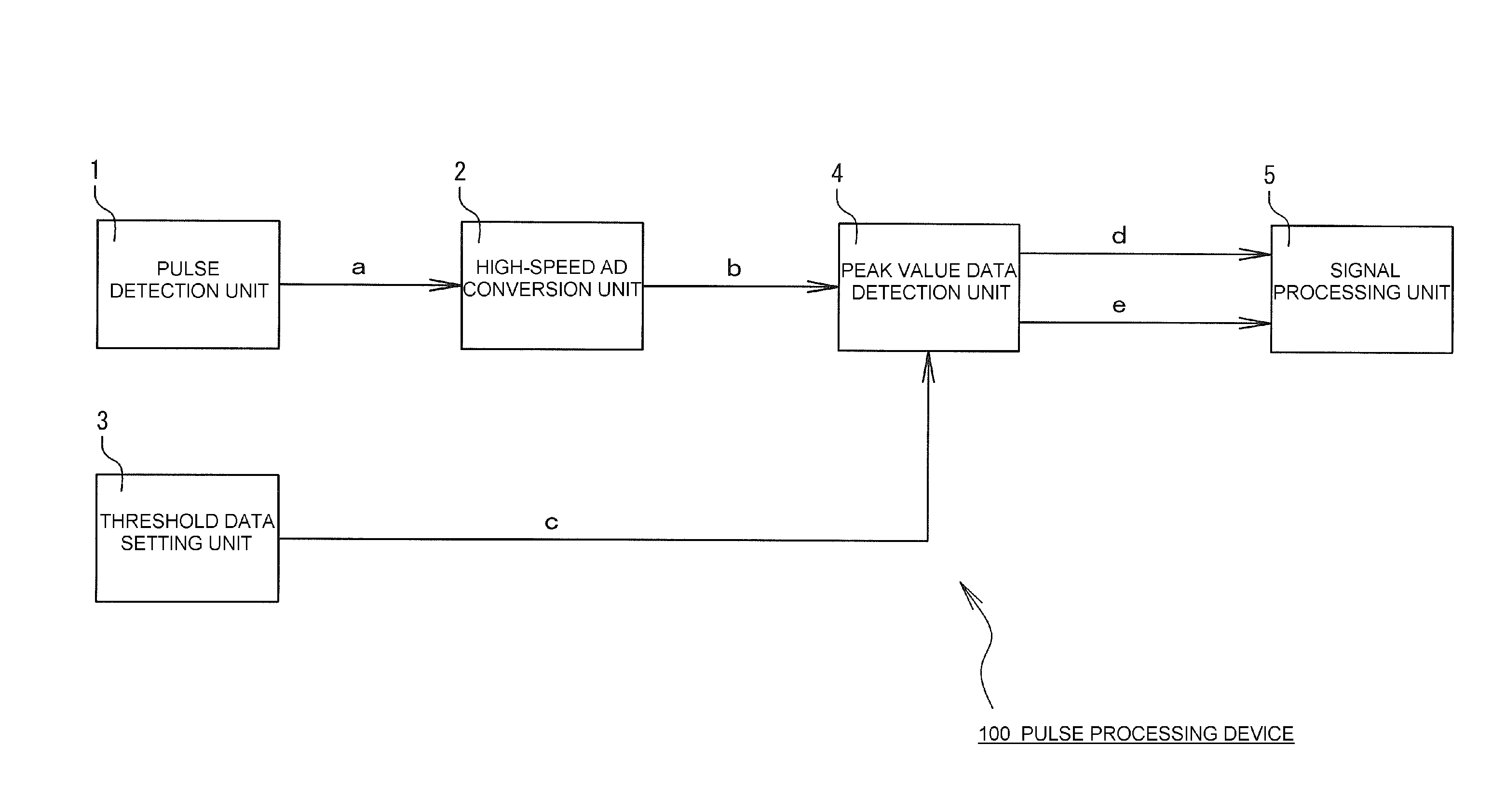
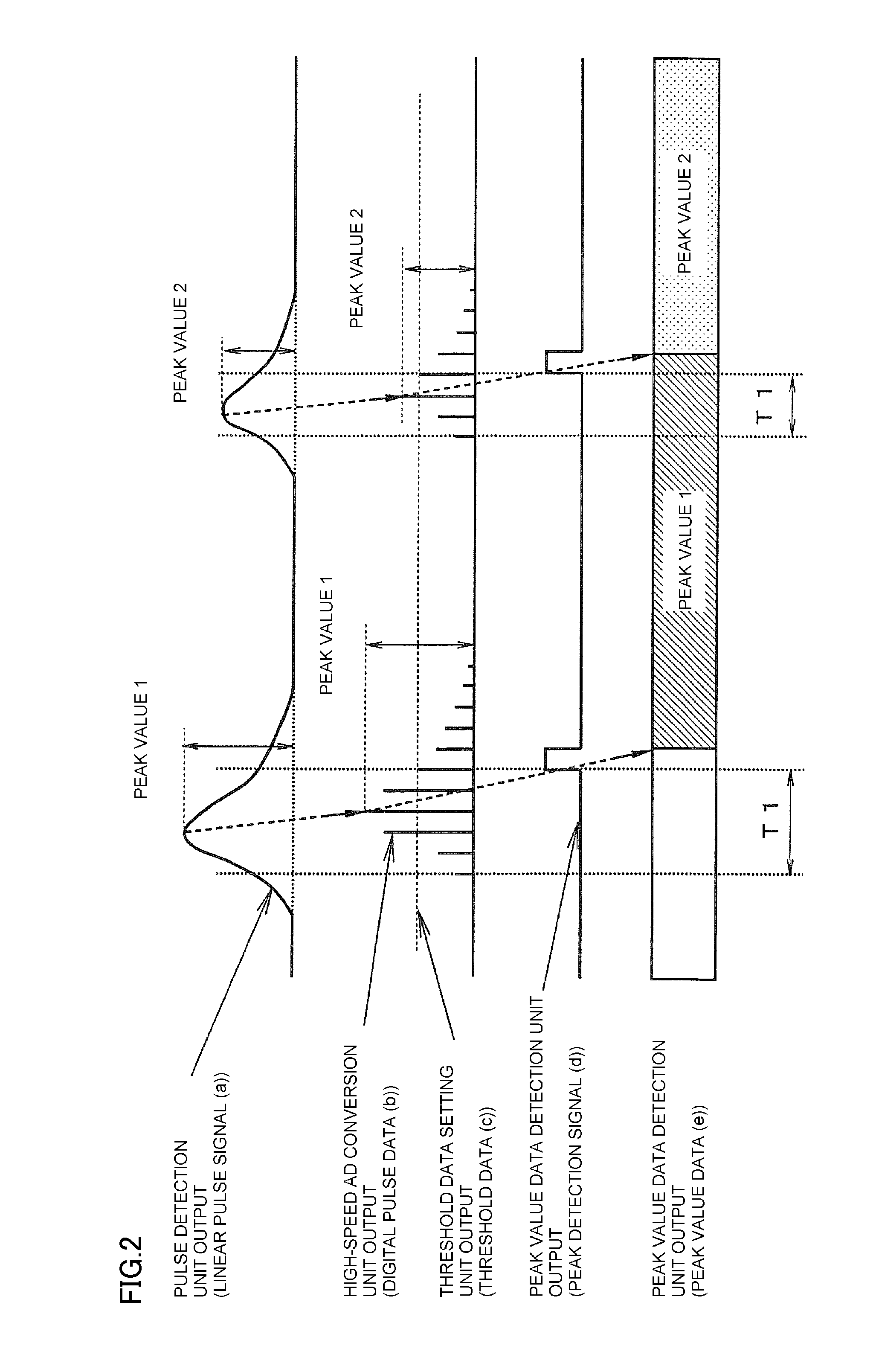
Provided is a pulse processing device that accelerates signal processing and prevents counting loss. Provided also is a radiation measuring device in which counting loss is prevented and counting capacity is increased by installing the pulse processing device. The processing device is in a form of a pulse processing device including a pulse detection unit that outputs a linear pulse signal in response to a physical event, a high-speed AD conversion unit that converts the linear pulse signal into digital pulse data, a threshold data setting unit that outputs preset threshold data, a peak value data detection unit that compares the digital pulse data with the threshold data and outputs the maximum digital pulse data, from among the digital pulse data continuously exceeding the threshold data, as maximum peak value data, and a signal processing unit that inputs the peak value data as a pulse wave height.

Description

TECHNICAL FIELD[0001]The present invention relates to a pulse processing device that processes pulses to facilitate pulse detection and a radiation measuring device incorporating the pulse processing device.DESCRIPTION OF THE RELATED ART[0002]The conventional radiation measuring instrument will be explained first. As shown in FIG. 27, a conventional radiation measuring instrument 600 is provided with a radiation detector 601, a threshold control circuit 602, a comparator 603, a peak hold circuit 604, an ADC 605, and a CPU 606. The outputs from those units are shown in a time chart in FIG. 28.[0003]The radiation detector 601 outputs a linear pulse signal A when radiation is detected. The comparator 603 inputs the linear pulse signal A from the radiation detector 601 and also inputs a threshold signal B from the threshold control circuit 602. The comparator 603 outputs a trigger signal C when the value of the linear pulse signal A exceeds the value of the threshold signal B.[0004]The ...

Claims


Application Information

Patent Timeline
Patent Type & Authority Applications(United States)
IPC IPC(8): G01R29/027
CPCG01R29/027G01T1/171G01T1/247
Inventor INOUE, TSUYOSHI
Owner FUJI ELECTRIC CO LTD
Learn More