Poppet valve with a formed seat, and method of making

a valve seat and poppet technology, applied in the field of poppet valves with formed seats, can solve the problems of seat cracking, repeated loads, and reduced seat cracking resistance, and achieve the effects of enhancing the resistance characteristics of the valve seat, preventing the galling of the outer circumference, and enhancing the wear resistan

Active Publication Date: 2014-07-10
NITTAN CORP
View PDF7 Cites 6 Cited by
  • Summary
  • Abstract
  • Description
  • Claims
  • Application Information

AI Technical Summary

Benefits of technology

[0009]Another aspect of the present invention allows one to form the poppet valve having the valve seat surface at a predetermined aperture angle, which is formed such that the rounded cladded part of the valve head of the poppet valve is made by way of welding so that the smooth surface is formed thereon by cutting the outer circumference of the valve head into a predetermined dimension concurrently with the cutting process, and the surface part thereof is plastically deformed. During the plastic working step, uniform contact pressure is applied at a temperature range possible for cold or warm forging of the smooth surface while being less than the recrystallization temperature of the base material of the valve body or the cladding material, whichever is lower, preventing the galling of the outer circumference from occurring. Accordingly, the valve seat can be work-hardened while at the same time maintaining compressive residual stress from the valve seat surface to a predetermined depth without grain coarsening with regard to both valve body and the valve seat. Also the welding defect can be solved. Thus characteristics of the cladding material are not impaired. Further, since said compressive stress acts as a drag on the tensile stress of the valve seat surface originating from the cutting process thereof, it becomes possible to enhance resistance characteristics of the valve seat against a fatigue breaking within the finishing process or engine operation, caused by the repeated stress while the engine is running or a seat-cracking caused by heat shock. As the valve seat is work-hardened, wear-resistance can be also enhanced.
[0010]Another aspect of the present invention allows one to form the valve seat of the poppet valve with less incidence of seat-cracking caused by the plastic working when the aperture angle of the valve seat surface is low, so that an excessive contact pressure is applied to the smooth surface at the time of plastic working, for example a poppet valve having a valve seat surface formed at an acute aperture angle of about 90-degrees or the like. This is because, at the time of forming the valve seat surface, the enlarged valve seat surface is integrally formed with the valve seat surface by forming the second smooth surface on the inner circumference of the valve seat surface so that the contact pressure applied on the valve seat surface can be reduced, resulting in the reduction of the incidence of seat-cracking on the valve seat.
[0011]Another aspect of the present invention allows one to form the poppet valve having the valve seat surface at a predetermined aperture angle, which is formed such that the valve head of the poppet valve is provided with the rounded cladded part made by way of welding so that the smooth surface is formed thereon by cutting the outer circumference of the valve head into a predetermined dimension concurrently with the cutting process, and the surface part thereof plastically deformed. In this plastic working process, uniform contact pressure is applied to the valve seat of the poppet valve at a temperature range possible for cold or warm forging of the smooth surface while being less than the recrystallization temperature of the base material of the valve body or the cladding material, whichever is lower, preventing the galling of the outer circumference from occurring. Accordingly, the valve seat can be work-hardened while concurrently maintaining compressive residual stress from the valve seat surface to a predetermined depth without grain coarsening of both the valve body and the valve seat. Also the welding defect can be solved. Thus characteristics of the cladding material are not impaired. Further, since said compressive stress acts as a drag on the tensile stress of the valve seat surface caused by the cutting process, the finishing process, or engine operation, it becomes possible to enhance the resistance characteristics against a fatigue breaking caused by repeated stress while the engine is running or a seat-cracking caused by heat shock. As the valve seat is work-hardened, wear resistance can be also enhanced.
[0012]Another embodiment of the present invention allows one to form the valve seat of the poppet valve with less incidence of seat-cracking caused by the plastic working when the aperture angle of the valve seat surface is low so as to be applied at an excessive forging contact pressure, for example with regard to a poppet valve having a valve seat surface formed at acute aperture angle of about 90-degree or the like. This is because, at the time of forming the first valve seat surface, the enlarged valve seat surface is also formed in the same manner by forming the second smooth surface on the inner circumference of the first valve seat surface at an aperture angle which is larger than that of the first valve seat surface so that the contact pressure applied on the valve seat surface can be reduced at the time of forging process.

Problems solved by technology

Accordingly, when tensile stress is loaded, e.g. at the time of finish processing, engine operation or the like, seat-cracking may be caused due to the resultant force of the remaining tensile stress.
In particular, while the engine is running, repeated loads occur due to the consecutive opening / closing of the valve.
Under such circumstances, it is inevitable that the characteristics of seat-cracking resistance are diminished.
As a result, there has been a problem ensuring the resistance characteristics corresponding to the cladding material.

Method used


Image

  • Poppet valve with a formed seat, and method of making
  • Poppet valve with a formed seat, and method of making
  • Poppet valve with a formed seat, and method of making

Examples


Embodiment Construction

[0019]Hereinafter, aspects of this invention based on the above-described technical idea will be concretely described with reference to the drawings.

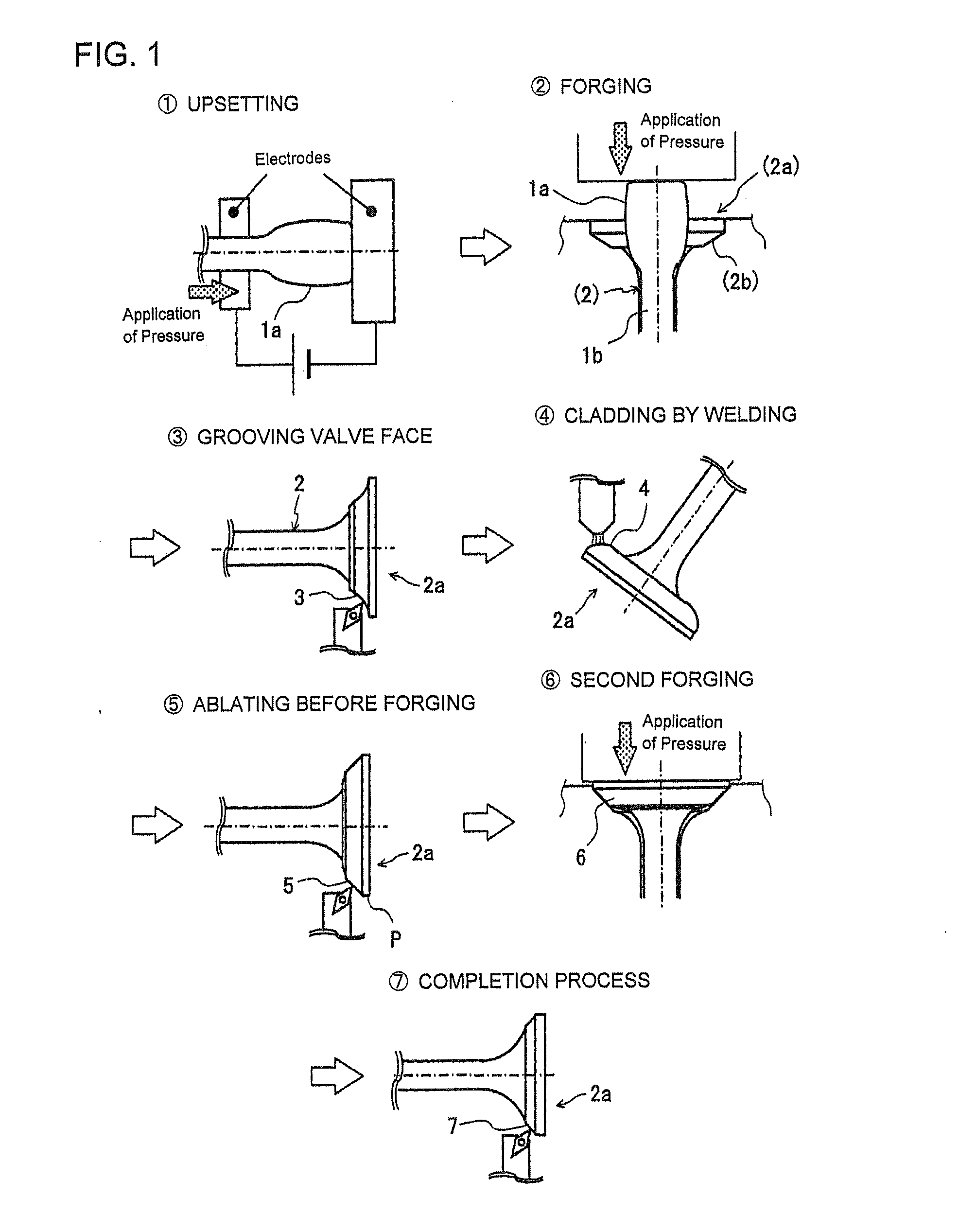
[0020]A poppet valve is comprised of a stem and a large-diameter valve head formed integrally thereto, which is manufactured by way of plastic working. Then a valve seat is formed on the valve head of the valve by a process of cladding by welding, which is eventually followed by a finishing process.

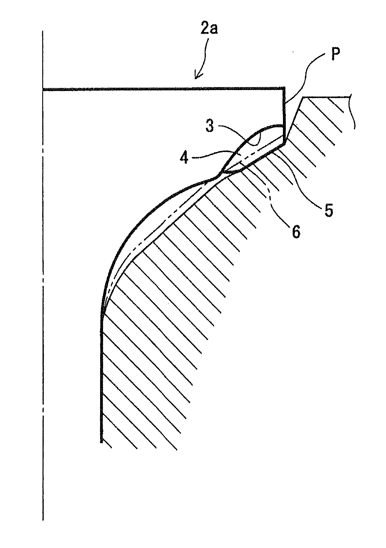
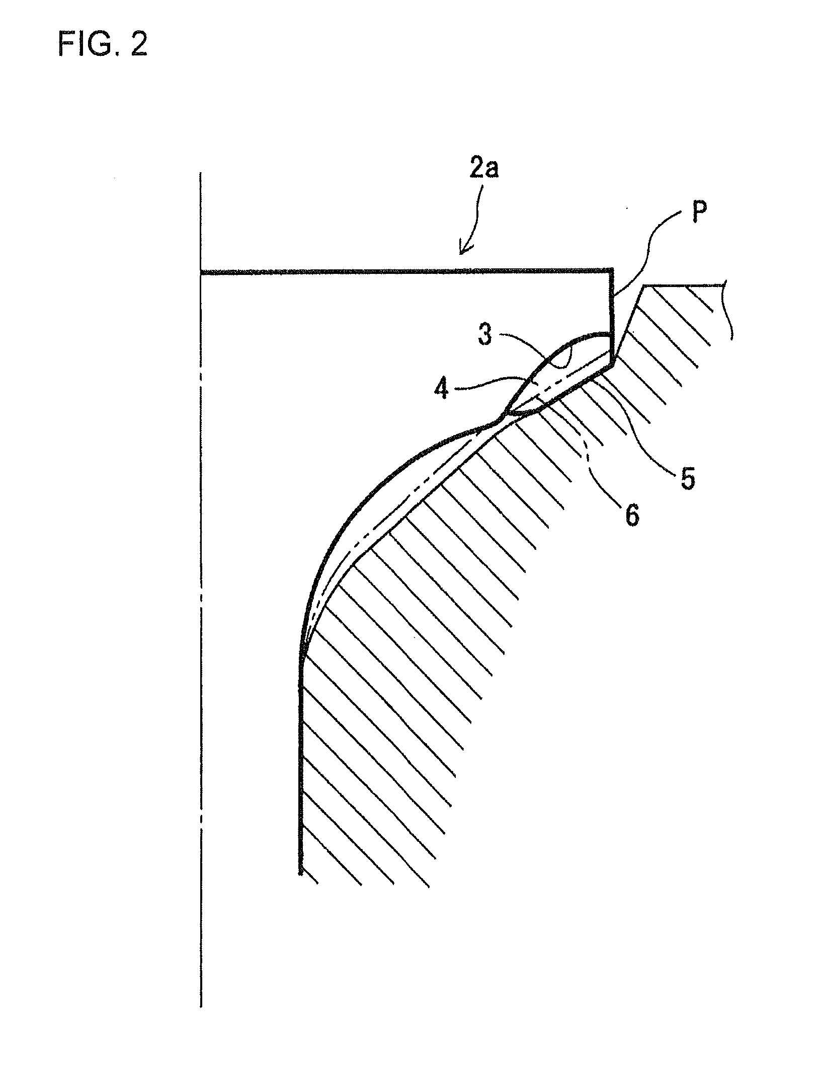
[0021]Among all manufacturing processes, the present invention has a primary feature with its valve seat forming process i.e. forming a cladding by welding an wear-resistant alloy on the valve head and then plastically deforming the valve seat. That is, it is characterized in that the valve head is provided with a groove for cladding so that the cladding by welding the wear-resistant alloy is carried out, and then the smooth surface is formed thereon through the cutting process. Subsequently uniform contact pressure is applied to the valve se...


PUM

PropertyMeasurementUnit
recrystallization temperatureaaaaaaaaaa
temperatureaaaaaaaaaa

Abstract

A method of forming a poppet valve having a stem, a valve head and a valve seat while concurrently maintaining compressive residual stress without grain coarsening on both the valve body and the valve seat. The method includes forming a rounded cladded part on the valve head of the poppet valve by welding and forming a valve seat surface at a predetermined aperture angle and cutting the cladded part to form a smooth surface which is subjected to uniform contact pressure at a temperature less than the recrystallization temperature of the base material or cladding material, whichever is lower, to enhance the durability of the valve seat.

Description

FIELD OF THE INVENTION[0001]The present invention relates to a poppet valve with a formed seat and a method of forming the poppet valve wherein a cladding by welding is formed at an valve head of the poppet valve body.BACKGROUND OF THE INVENTION[0002]Because the valve seat of a poppet valve is subjected to repeated impacts from a valve seat in a cylinder head, technologies which enhance the durability thereof have been used as are disclosed in Patent document 1 below. That is, when manufacturing a poppet valve, a cladding by welding wear-resistant alloy is formed at a valve head thereof so as to form a valve seat.Patent Document 1:Japanese Patent Application Laid-Open No. 2011-101897SUMMARY OF THE INVENTION[0003]Although said valve seat can be hardened by the cladding material welded thereon, it is known that tensile stress remains inside of the valve seat because of the thermal stress caused by the cladding by welding, the differential thermal expansion between the cladding materia...

Claims


Application Information

Patent Timeline
Patent Type & Authority Applications(United States)
IPC IPC(8): F16K1/42
CPCF16K1/42B21K1/22B23P15/002F01L3/00F01L3/04F01L2303/00Y10T137/0491Y10T137/0497B23K9/04B23K31/00
Inventor MIKAMI, MAIKUKURAHASHI, KAZUNORI
Owner NITTAN CORP
Why Eureka
Try Eureka