Apparatus and a method for testing winding resistances of transformers

a transformer and winding resistance technology, applied in the direction of resistance/reactance/impedence, measurement devices, instruments, etc., can solve the problems of time-consuming, difficult to measure the resistance of delta-connected windings in transformers, and the balancing process may take several minutes up to one hour, so as to reduce the measurement time

Active Publication Date: 2014-07-10
HAEFELY TEST
View PDF4 Cites 17 Cited by
  • Summary
  • Abstract
  • Description
  • Claims
  • Application Information

AI Technical Summary

Benefits of technology

[0008]Hence, it is a general object of the invention to provide a measurement

Problems solved by technology

The resistance of Delta-connected windings in transformers is difficult to measure and it can be very time consuming.
On large generator transformers, this balancing process may for example take several minutes up to one hour.
These high current testers of the prior art are large and h

Method used


Image

  • Apparatus and a method for testing winding resistances of transformers
  • Apparatus and a method for testing winding resistances of transformers
  • Apparatus and a method for testing winding resistances of transformers

Examples


first embodiment

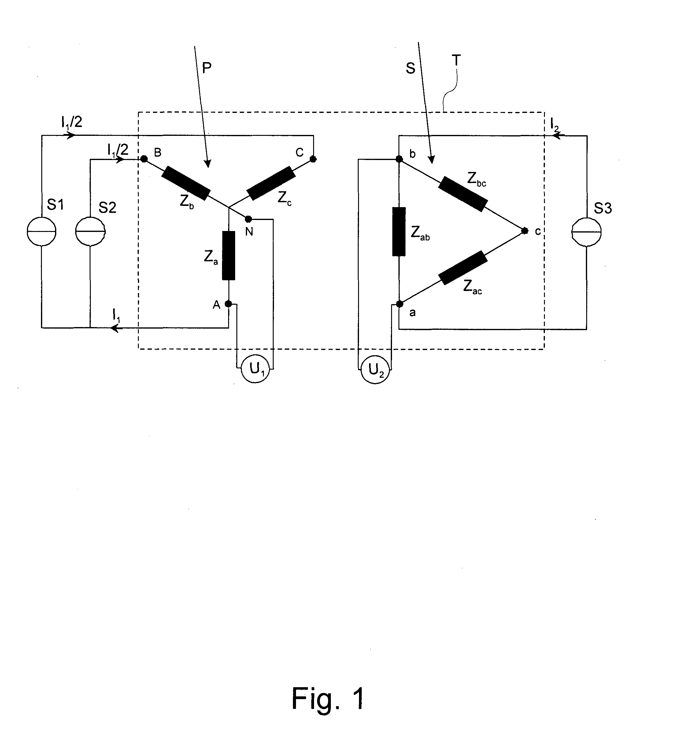
[0020]FIG. 1 shows an example of the measurement method in the apparatus according to the invention with a first, a second and a third current source S1, S2, S3 connected to a ‘YNd’-three-phase transformer T. The primary side or high voltage side of the transformer is denoted by P and the secondary side or low voltage side is denoted by S. In this exemplary configuration, the primary side P has a star topology, wherein A, B, C denote phase ends of the three phases and N denotes a neutral reference node. Za, Zb, Zc illustrate the impedances of the winding of each phase. The impedances are to be seen as a resistance R and an inductance L coupled in series, as known. The topology of the secondary side S is in this exemplary case a Delta topology having three nodes a, b, c, each of which connects two legs of this Delta-layout. Zab, Zbc, Zac illustrate the impedances of the winding of each leg. The impedances are also to be seen as a resistance R and an inductance L coupled in series, as...

second embodiment

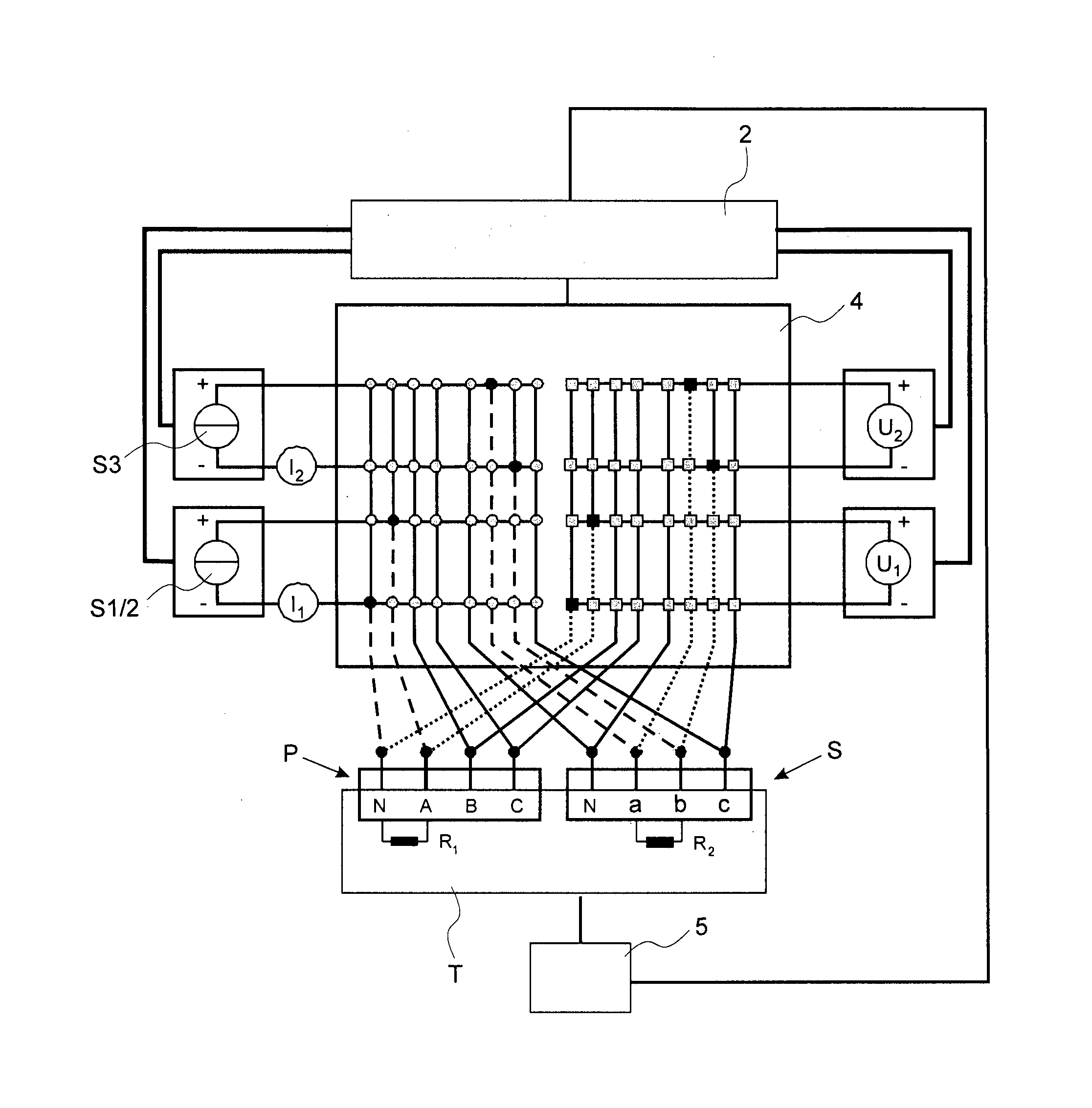
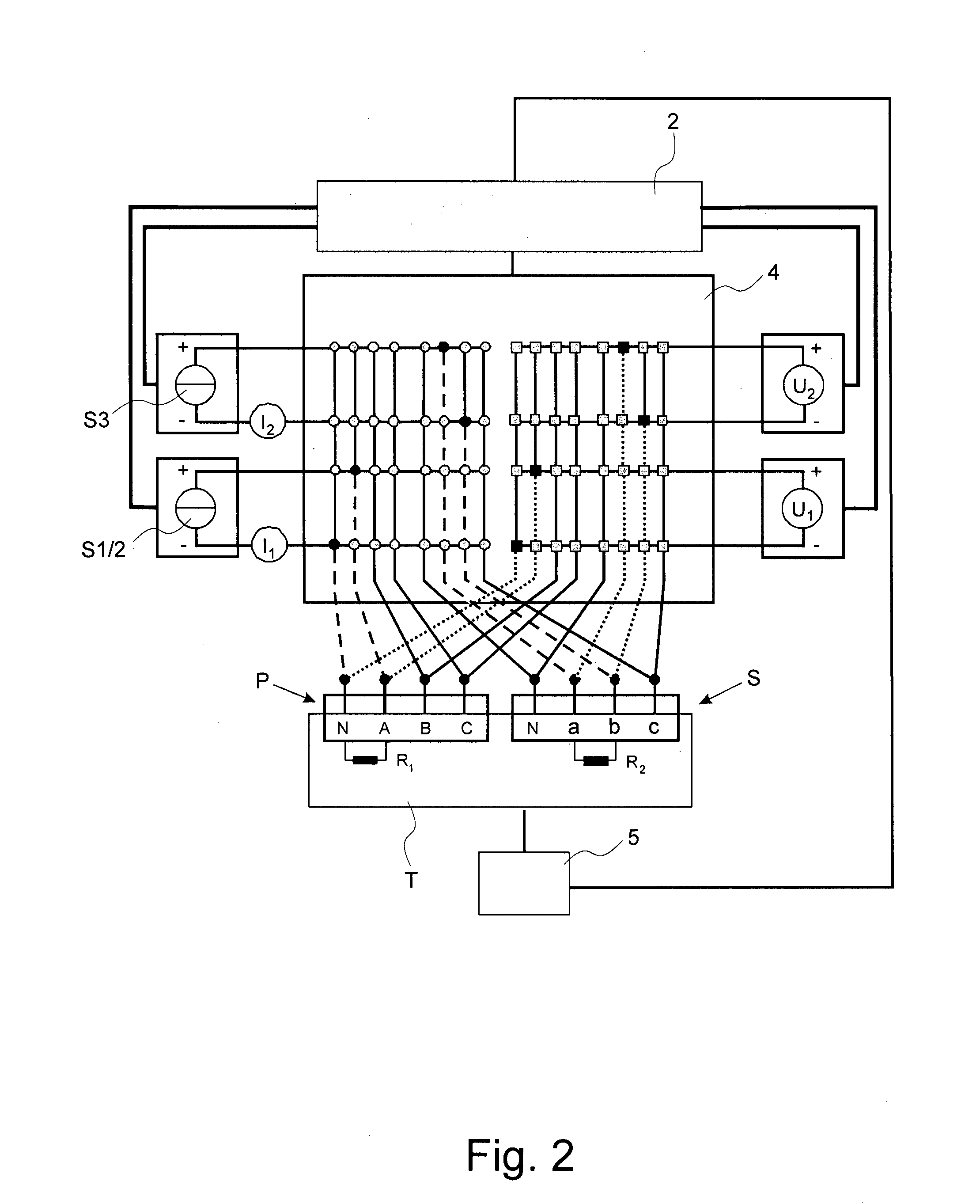
[0028]FIG. 2 shows a block schematic of the apparatus according to the invention, which is connected to a three-phase ‘YNd’-transformer T. The transformer has a primary, high voltage side P and a secondary low voltage side S. The primary side has a star topology, wherein A, B, C denote phase ends of the three phases and N denotes an optional neutral reference node. The topology of the secondary side S is in this exemplary case a Delta topology having three nodes a, b, c, each of which connects two legs of the Delta-layout and an optional neutral reference point N. The topology of the transformer can be seen in a schematic illustration in FIG. 1. In FIG. 2, the apparatus of FIG. 1 is extended by a multiplexer 4 connecting the DC current sources S1, S2, S3 to the transformer. The multiplexer 4 comprises a connection matrix denoted by circles and squares and their interconnections in FIG. 2. This switching connection matrix allows a plurality of different, selectable connections betwee...


PUM


Abstract

The present invention relates to an apparatus for measuring winding resistances of windings in a delta-connected transformer, comprising at least a first and a second DC current source (S1, S2) connected each between the phase ends of a first (A) and a second leg (C; B) respectively of the primary side (P) of the transformer and at least a third DC current source (S3) connected between two nodes (a, b) of the secondary side (S) of the transformer. Furthermore the invention relates to a method for measuring a winding resistance of windings in delta-connected transformers, comprising the steps of applying a first and a second measuring current to each one of two corresponding legs (C, B), applying a third measuring current (I2) between two nodes (b, a) of a pair of windings on the secondary side (S) and measuring at least a winding resistance of the winding between said nodes (b, a) on the secondary side (S) of the transformer and/or the winding resistance of a leg (A) of the primary side (P) as soon as an inductive voltage drop in the windings substantially equals zero.

Description

CROSS REFERENCE TO RELATED APPLICATIONS[0001]This application claims the priority of international patent application PCT / CH2O11 / 000113, filed May 17, 2011, the disclosure of which is incorporated herein by reference in its entirety.TECHNICAL FIELD[0002]The present invention is related to an apparatus and a method for testing transformers according to the respective independent claims. In particular, the invention describes a method and apparatus for testing winding resistances of transformers, particularly Delta-connected transformers.BACKGROUND ART[0003]The phenomenon of ferromagnetic saturation plays an important role in the prior art high current transformer resistance meters. The main inductance L of the transformer drastically drops when the magnetic core is saturated. This effect facilitates it to measure the ohmic resistance after the inductive voltage drop has decayed to zero.[0004]The resistance of Delta-connected windings in transformers is difficult to measure and it can...

Claims


Application Information

Patent Timeline
IPC IPC(8): G01R31/06G01R31/62G01R31/72
CPCG01R31/06G01R27/14G01R31/62G01R31/72
Inventor MULLER, MARC
Owner HAEFELY TEST
Why Eureka
Try Eureka