
Method and apparatus for indicating downlink channel measurement and method and apparatus performing downlink channel measurement in a relaying system

a relaying system and channel measurement technology, applied in the field of mobile communication technology, can solve the problems of interference in the access subframe, the technical solution proposed in the us patent may not work well, and the interference on the own receiver, so as to achieve more accurate and reliable scheduling, the effect of reducing the number of delays

Active Publication Date: 2014-07-10
NEC CORP
View PDF2 Cites 16 Cited by
  • Summary
  • Abstract
  • Description
  • Claims
  • Application Information

AI Technical Summary

Benefits of technology

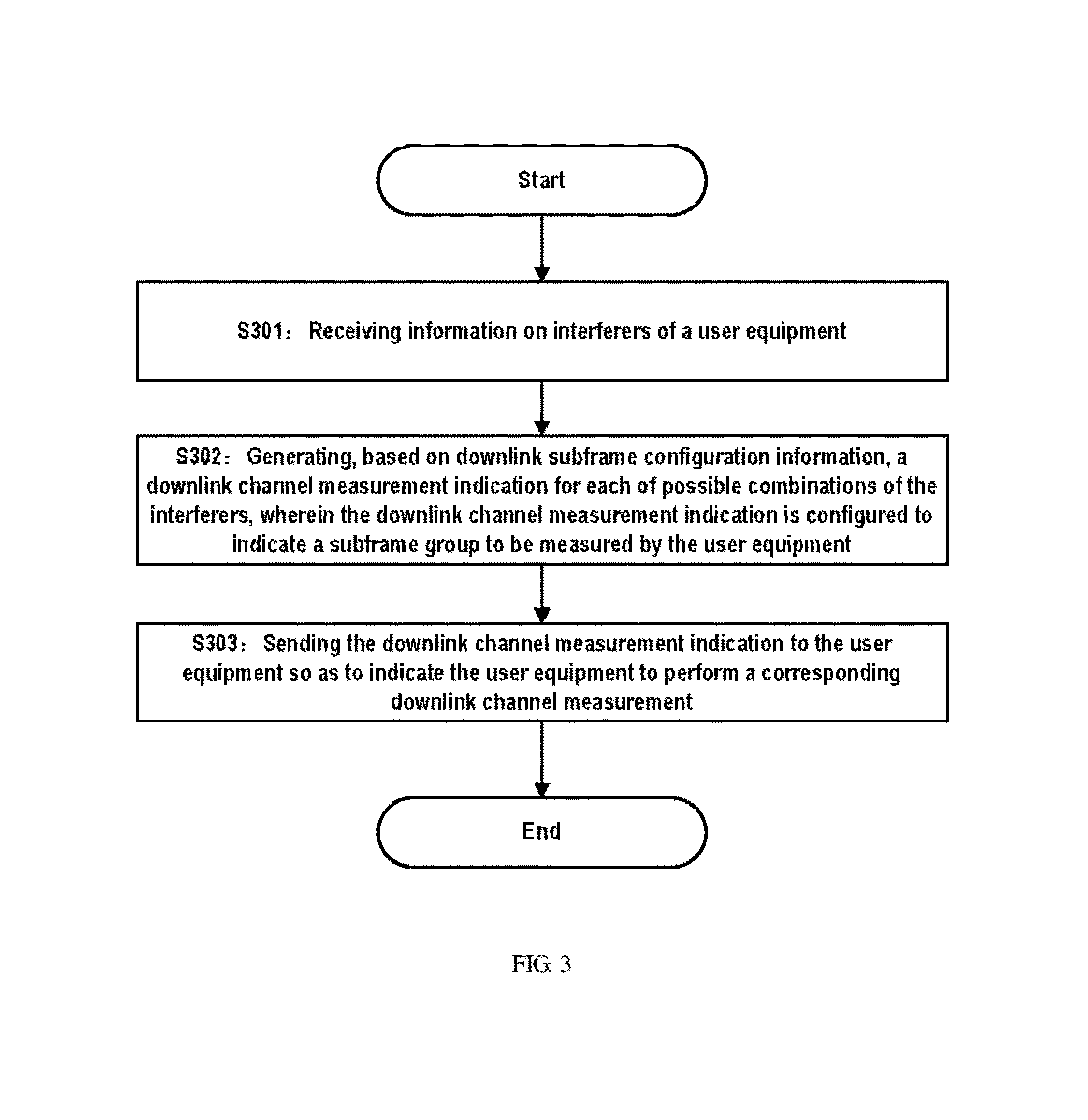
The present invention provides a method for more accurately and reliably measuring channel quality in a wireless communication system. This involves grouping together subframes that are subjected to the same level of interference and transmitting these groups as measurement indications to user equipment. This allows the user equipment to perform channel quality measurement for each subgroup, leading to better accuracy and efficiency in channel scheduling.

Problems solved by technology

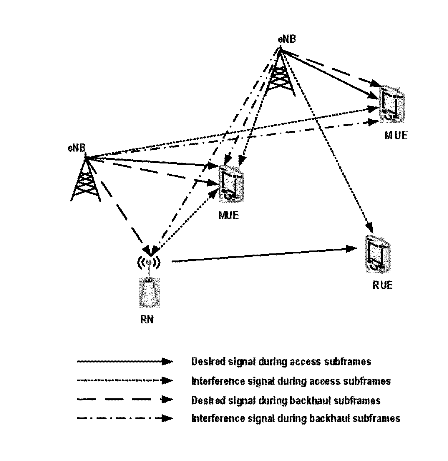
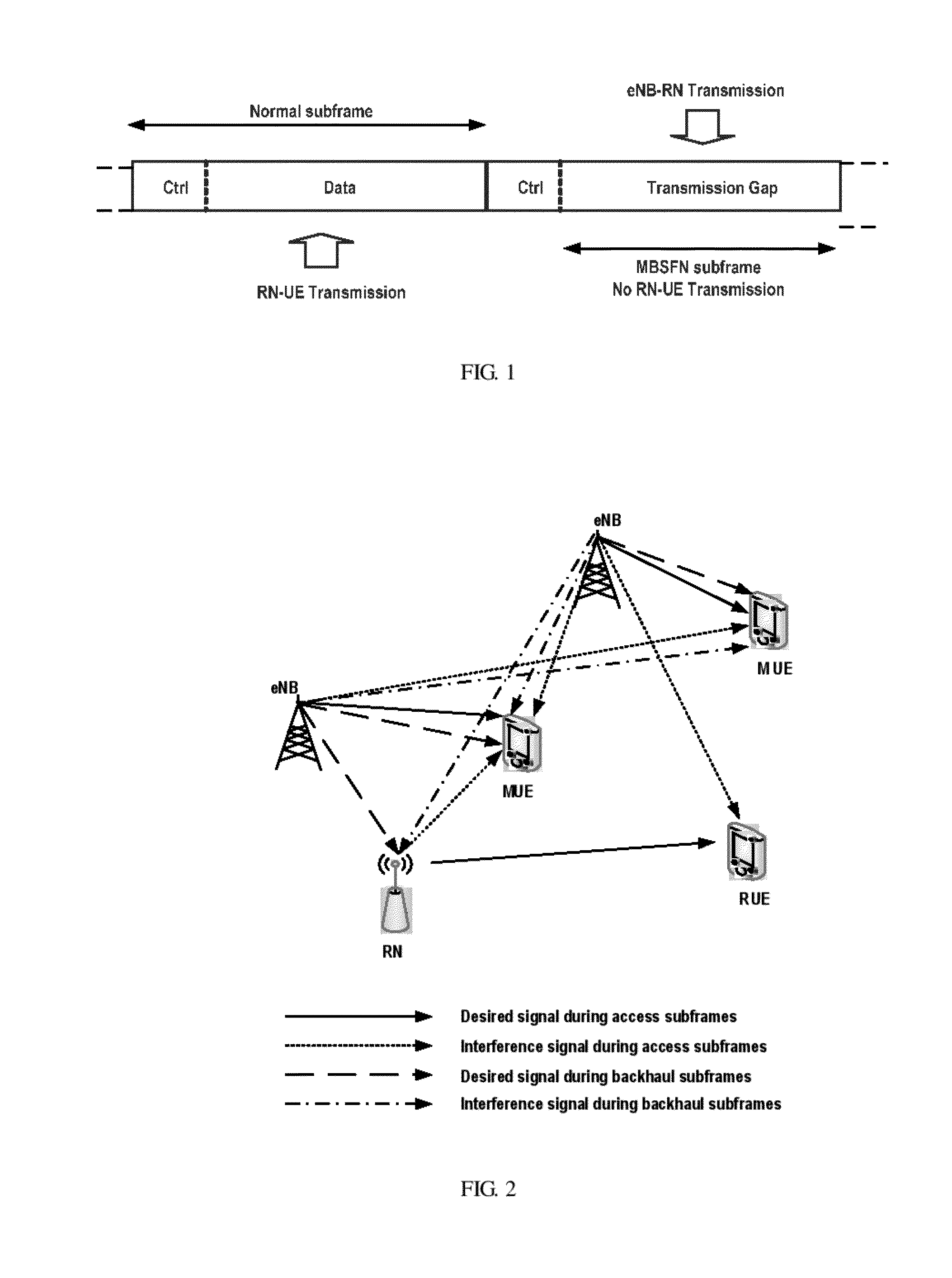
Because the above “Type 1” relay node is an inband relay node, the backhaul link and the access link will use the same frequency band and thus the relay transmitter will cause interference on its own receiver.
In this case, the interference in these access subframes comes from both RNs and eNBs.
Thus, the technical solution as proposed in the US patent may not work well in this case, due to measurement mismatch with the actual interference condition.

Method used


Image

  • Method and apparatus for indicating downlink channel measurement and method and apparatus performing downlink channel measurement in a relaying system
  • Method and apparatus for indicating downlink channel measurement and method and apparatus performing downlink channel measurement in a relaying system
  • Method and apparatus for indicating downlink channel measurement and method and apparatus performing downlink channel measurement in a relaying system

Examples


Embodiment Construction

[0040]Hereinafter, a method and apparatus for indicating downlink channel measurement and a method and apparatus for performing downlink channel measurement as provided in the present invention will be described in detail through embodiments with reference to the accompanying drawings. It should be understood that these embodiments are presented only to enable those skilled in the art to better understand and implement the present invention, not intend for limiting the scope of the present invention in any manner.

[0041]It should be first noted that this invention is illustrated in particular sequences for performing the steps of the methods. However, these methods are not necessarily performed strictly according to the illustrated sequences, and they can be performed in reverse sequence or simultaneously based on natures of respective method steps. Beside, the indefinite article “a / an” as used herein does not exclude a plurality of such steps, units, devices, and objects, and etc.

[0...


PUM


Abstract

The present invention provides a method and apparatus for indicating downlink channel measurement and a method and apparatus for performing channel measurement. The method for indicating downlink channel measurement comprises: receiving information on interferes of a user equipment; generating, based on downlink subframe configuration information, a downlink channel measurement indication for each of possible combinations of the interferers, wherein the channel measurement indication is adapted to indicate a subframe group to be measured by a user equipment; and sending the downlink channel measurement indication to the user equipment so as to indicate the user equipment to perform corresponding downlink channel measurement. According to embodiments of the present invention, the subframe groups that are required to be measured by the user equipment may be determined with respect to possible combinations of interferers corresponding to different levels of interference. Thus, the user equipment may perform channel measurement for respective subframe groups. Therefore, the channel quality as determined in such way will be more accurate and reliable and better match the actual channel condition. Moreover, it also provides a possibility for the serving node to perform the scheduling more accurately and effectively.

Description

TECHNICAL FIELD[0001]The present invention relates to the field of a mobile communication technology, and more particularly, relates to a method and apparatus for indicating downlink channel measurement in a relaying system and a method and apparatus for performing downlink channel measurement in a relaying system.BACKGROUND[0002]In 3GPP long-term evolution advanced (3GPP LTE-A) technology, the relay technology is adopted. The relay is a technology that processes and forwards received signals by a relay node to thereby expand radio coverage and enhance data throughput. The relay technology may improve the coverage of high data rate, group mobility, temporary network deployment and the throughput of a cell edge, and may also be used to provide the coverage in new areas. With the relay technology, a relay node (RN) divides a direct link from a base station (eNB) to a user equipment (UE) with a relatively poor quality into two links with relatively good qualities, i.e., an access link ...

Claims


Application Information

Patent Timeline
Patent Type & Authority Applications(United States)
IPC IPC(8): H04W24/10
CPCH04W24/10
Inventor YI, SUZHANG, YUSUN, ZHENNIANLEI, MING
Owner NEC CORP
Learn More