
Jet Spouted Bed Type Reactor Device Having A Specific Profile For CVD

Active Publication Date: 2014-07-10
COMMISSARIAT A LENERGIE ATOMIQUE ET AUX ENERGIES ALTERNATIVES
View PDF2 Cites 3 Cited by
  • Summary
  • Abstract
  • Description
  • Claims
  • Application Information

AI Technical Summary

Benefits of technology

The patent describes a new way to transfer gas to a reactor, which reduces the amount of solid material that needs to be liquefied. This improves the control and sensitivity of the coating process. The new method also minimizes the risk of blockages and sticking at the gas injector. Overall, this leads to a more efficient and effective coating process.

Problems solved by technology

Jet spouted bed type reactors, on the one hand, and fluidised bed type reactors, on the other hand, thus do not at all have the same hydrodynamics, are not optimised in the same way and the optimisation of one of the 2 types does not enable the optimisation of the other type.
This phenomenon of fluidisation is not however easy for all types of particles, as has been shown by Geldart in his classification of powders (Geldart D.
But, in the case where there is a constraint to implement a reduced mass of charge (case of expensive material or which could lead to a risk of criticality, for example) important edge effects become manifest.
In fact, it can then not be envisaged to reduce in an ill-considered manner the diameter of the reactor, because edge effects (influences of the wall on the flow of the powder) are not negligible up to a distance to the wall substantially less than or equal to at least 10 times the diameter of the particles to be fluidised.
Thus, it is not possible to reduce the reactor diameter too much without perturbing a high proportion of the flow of the powders.
These devices are optimised for a specific method of application, but are not very well suited for the case of an implementation of material, such as a nuclear material, not allowing frequent interventions / maintenances during the implementation of solutions as sophisticated and less robust than the simplified profiles described previously.
Moreover, as for the cases described above, these profiles do not make it possible to minimise the volume Vo, a relevant criterion particularly in the case of an implementation of a limited quantity of material, as already evoked above.
The problem is thus posed of being able to carry out one or several depositions, in particular by CVD technique, on a charge that is difficult to fluidise, particularly in the sense given by Geldart, also leading to a high risk of clogging and / or plugging, particularly at the level of the injection of gas (in other words the dimension Z0).
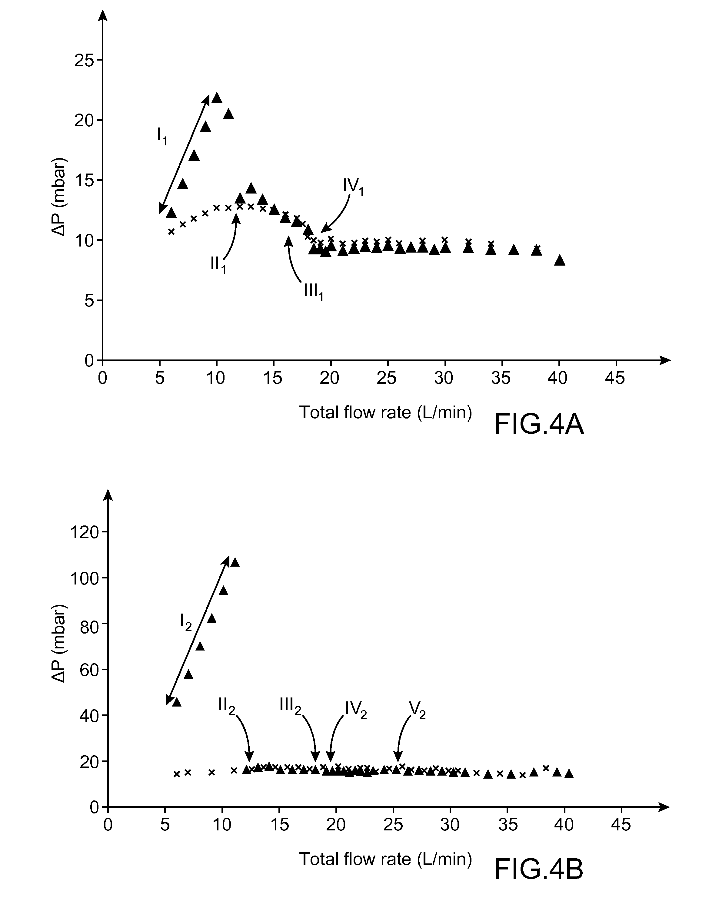
A powder may also be considered as difficult to fluidise if the minimal gas velocity, necessary for this fluidisation, is very high and if the phenomenon is not very reproducible or at least very sensitive to slight thermohydraulic variations or characteristics of the powders; one also speaks of not very easy fluidisation when the head loss brought about by a gaseous flow through the bed to be fluidised is fluctuating, despite a slight increase in the flow velocity of the gas through the bed of powder to be fluidised.
In this case, this important variation of characteristics of the charge during deposition (and because of the very fact of the latter) may be very disadvantageous because the conditions of fluidisation of the charges are going to be, consequently, modified.
3 constraints need moreover to be taken into account:the first is the fact that the charge on which the deposition must be carried out is assumed, by virtue of said deposition, to vary significantly in terms of apparent density and granulometry,the second resides in the fact that the charge on which the deposition has to be carried out is necessarily of limited mass, due to the fact that this charge is, for example, very expensive and / or liable to lead to a risk of criticality,the third resides in the desire to limit the risks of plugging at the bed / emerging gas injector interface.
No known structure of jet spouted bed exists that responds to this complex problem.

Method used


Image

  • Jet Spouted Bed Type Reactor Device Having A Specific Profile For CVD
  • Jet Spouted Bed Type Reactor Device Having A Specific Profile For CVD
  • Jet Spouted Bed Type Reactor Device Having A Specific Profile For CVD

Examples


Embodiment Construction

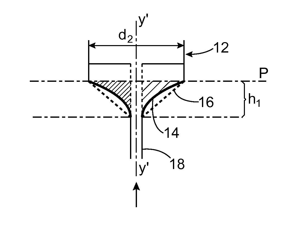
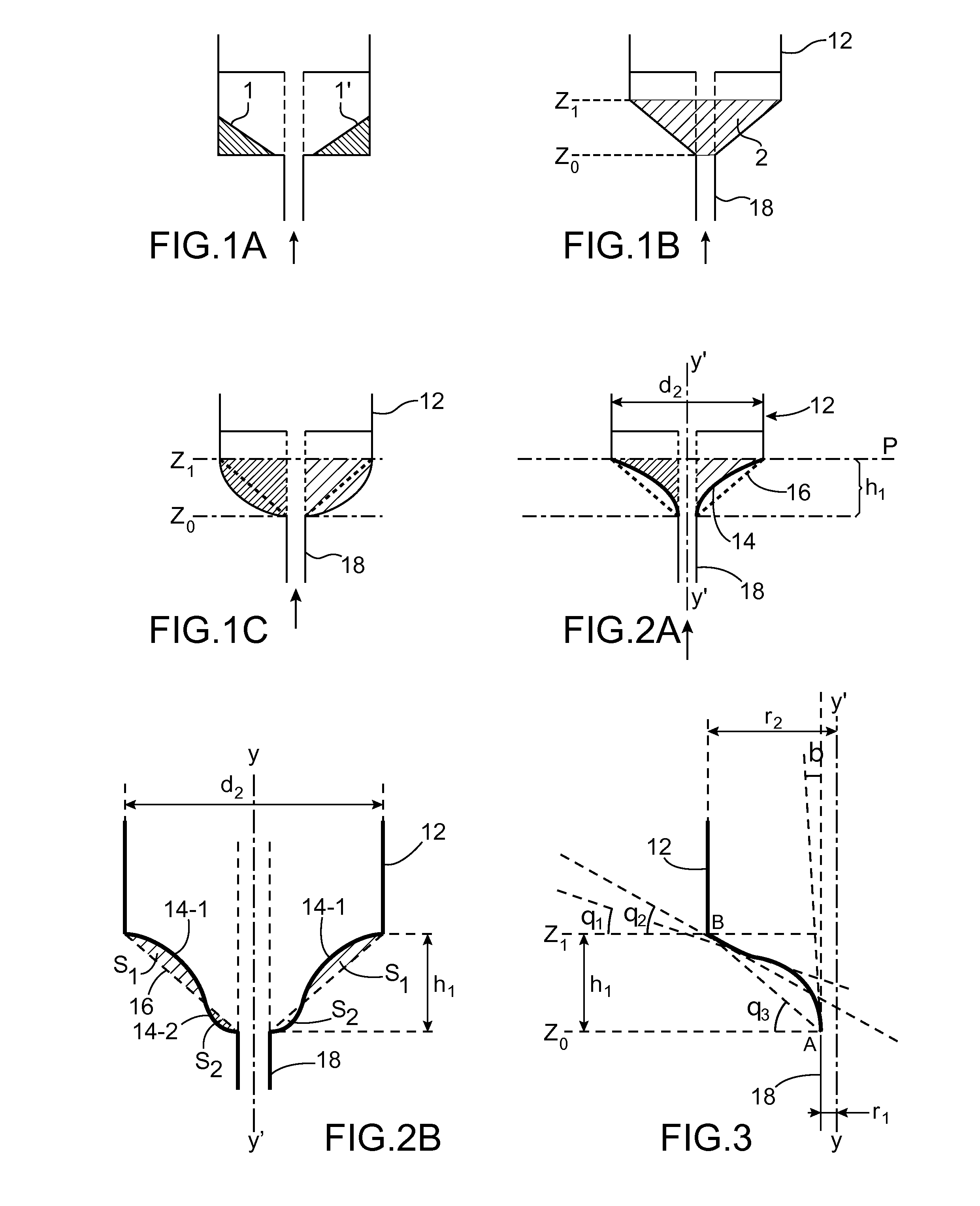
[0035]A jet spouted bed reactor is described herein, comprising a cylindrical area, a single gas injection pipe at the base of the cylindrical area, and a transition area, connecting the upper end of the pipe to the base of the cylindrical area, this transition area having a predominantly convex profile in a plane extending through the axis of flow of a fluid in the pipe.

[0036]The profile may have areas of convexity and areas of non-convexity; but the areas of non-convexity are predominant, in other words that their areas (or volumes if 3D is considered) as defined, compared to the hollowing out of a conical straight profile, are greater than those of convex areas.

[0037]One thus describes a new transition profile between the injection section of the gas of the jet spouted bed and the cylindrical terminal section (or lower) of the reactor, which makes it possible to minimise the volume of solid to be fluidised which is not comprised in the cylindrical section (volume Vo). This makes ...


PUM

PropertyMeasurementUnit
Angleaaaaaaaaaa
Angleaaaaaaaaaa
Angleaaaaaaaaaa

Abstract

The invention relates to a jet spouted bed reactor, comprising a cylindrical area, a gas injection pipe at the base of the cylindrical area, and a transition area, connecting the upper end of the pipe to the base of the cylindrical area, this transition area having a convex profile in a plane extending through the axis (YY′) of flow of a fluid in the pipe.

Description

TECHNICAL FIELD AND PRIOR ART[0001]Within the scope of methods implementing a deposition on powders or particles by techniques of the type known as CVD (Chemical Vapour Deposition), it is sometimes necessary, depending on the characteristics of the granular material on which it is wished to carry out the deposition, to implement a fluidisation by jet spouted bed. This implementation enables an efficient mixing (and thus a homogeneous deposition) of the bed of powder despite the difficulty of fluidising the latter. The present invention proposes a specific conception of jet spouted bed reactor enabling an improvement of the control of the deposition conditions for cases inducing a significant modification of the characteristics of the bed by the very fact of this deposition. This is typically the case of jet spouted bed type reactors dedicated to the elaboration of fuel particles that can be used (TRISO particles) for HTR (High Temperature Reactor) type reactors.[0002]It will be reca...

Claims


Application Information

Patent Timeline
IPC IPC(8): G21C3/20
CPCG21C3/20C23C16/4417C23C16/442C23C16/455G21C3/623G21C21/02Y02E30/10Y02E30/30
Inventor BROTHIER, MERYLMOULINIER, DOMINIQUERODRIGUEZ, PHILIPPEABLITZER, CARINE
Owner COMMISSARIAT A LENERGIE ATOMIQUE ET AUX ENERGIES ALTERNATIVES
Learn More