Method for operating an exhaust gas recirculation system

a technology of exhaust gas recirculation and egr, which is applied in the direction of mechanical equipment, machines/engines, and non-fuel substance addition to fuel, etc., can solve the problems of preventing the thermal system from reaching temperatures sufficiently high, affecting engine performance, and affecting the performance of the engin

Inactive Publication Date: 2014-07-17
GM GLOBAL TECH OPERATIONS LLC
View PDF5 Cites 6 Cited by
  • Summary
  • Abstract
  • Description
  • Claims
  • Application Information

AI Technical Summary

Benefits of technology

[0014]According to another embodiment, the method comprises the further steps of: monitoring a parameter representative of a thermal load of the thermal energy source, and bypassing the EGR cooler if the parameter is lower than a first target value thereof representative of low thermal load conditions. At least one advantage of this embodiment is that it allows to heat up the EGR coolant at low thermal load conditions.
[0015]According to still another embodiment, the method comprises the further steps of: repeating the activation and deactivation steps of the EGR coolant pump if the parameter representative of a thermal load of the thermal energy source is higher than the first target value thereof and lower than a second target value thereof representative of the end of a warm up phase of the thermal energy source. At least one advantage of this embodiment is that it allows control of the EGR coolant temperature in an important phase of the driving profile considering that the driving profile is not known a priori.
[0016]According to a further embodiment, the thermal energy source is an internal combustion engine. An advantage of this embodiment is that the method can be applied in a wide variety of automotive systems.
[0017]According to a further embodiment of the method, the predetermined values of the activation time and of the deactivation time of the EGR coolant pump are determined by means of an empirically determined map correlating different values of the activation time and of the deactivation time to different values of engine speed, engine load, engine temperature, EGR gas flow in the EGR circuit, environmental temperature and pressure. At least one advantage of this embodiment is that it allows memorization of the pattern of activation and deactivation of the EGR coolant pump to be used during different driving profiles.
[0018]According to a further embodiment of the method, the parameter indicative of a thermal load of the engine is a function of engine temperature, engine speed and engine torque. At least one advantage of this embodiment is that it allows identification and takes into account the main variables that affect the thermal load of the engine and use these variables to control the bypassing of the EGR cooler.
[0019]An Exhaust Gas Recirculation (EGR) system of a thermal energy source is provided for use in the method according to the above embodiments, the EGR system comprising an EGR circuit and an EGR cooler, the EGR cooler being connected in a heat exchanging relationship with an EGR coolant circuit equipped with an EGR coolant pump. The EGR circuit and the EGR cooler have portions that are adjacent to each other to form a heat exchange area for the exhaust gas. At least one advantage of this embodiment is that the presence of the heat exchange area is allowed to heat up the EGR coolant during warm up of the engine.

Problems solved by technology

A problem that may arise in the use of high efficiency EGR systems is that exhaust gas condensation may occur.
More specifically, exposure to low exhaust gas temperatures that occurs at low thermal load conditions and / or during interrupted running profiles, prevents the thermal system to reach temperatures sufficiently high to avoid condensation in the EGR system components.
This problem is particularly relevant since during normal driving conditions the driver profile is not known a priori.
Gas condensation may lead to EGR cooler clogging, causing a negative impact on engine performance.

Method used


Image

  • Method for operating an exhaust gas recirculation system
  • Method for operating an exhaust gas recirculation system
  • Method for operating an exhaust gas recirculation system

Examples


Embodiment Construction

[0031]The following detailed description is merely exemplary in nature and is not intended to limit application and uses. Furthermore, there is no intention to be bound by any theory presented in the preceding background or the following detailed description.

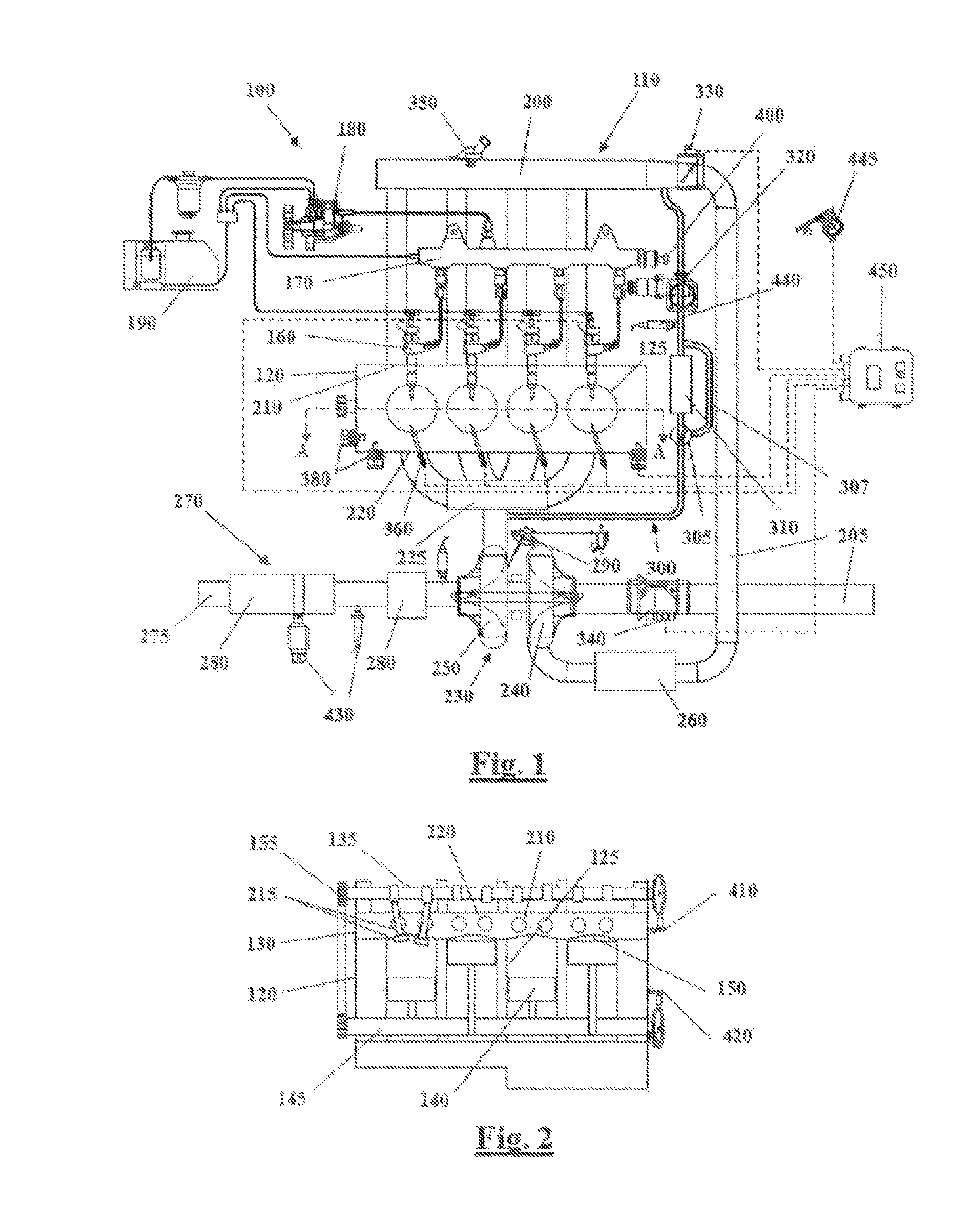
[0032]Some embodiments may include an automotive system 100, as shown in FIG. 1 and FIG. 2, that includes an internal combustion engine (ICE) 110 having an engine block 120 defining at least one cylinder 125 having a piston 140 coupled to rotate a crankshaft 145. A cylinder head 130 cooperates with the piston 140 to define a combustion chamber 150. A fuel and air mixture (not shown) is disposed in the combustion chamber 150 and ignited, resulting in hot expanding exhaust gasses causing reciprocal movement of the piston 140. The fuel is provided by at least one fuel injector 160 and the air through at least one intake port 210. The fuel is provided at high pressure to the fuel injector 160 from a fuel rail 170 in fluid communicat...


PUM


Abstract

A method is provided for operating an Exhaust Gas Recirculation (EGR) system of a thermal energy source, the EGR system includes, but is not limited to an EGR circuit and an EGR cooler, the EGR cooler connected in a heat exchanging relationship with an EGR coolant circuit equipped with an EGR coolant pump. The method includes, but is not limited to monitoring a parameter (TEGRcool) representative of a temperature of the coolant in the EGR coolant circuit, operating the EGR coolant pump on the basis of the parameter (TEGRcool) and of a target value thereof (TEGRtgt).

Description

CROSS REFERENCE TO RELATED APPLICATION[0001]This application claims priority to GB Patent Application No. 1300481.7, filed Jan. 11, 2013, which is incorporated herein by its entirety.TECHNICAL FIELD[0002]The technical field relates to a method for operating an Exhaust Gas Recirculation (EGR) system.BACKGROUND[0003]An internal combustion engine for a motor vehicle generally comprises an engine block that defines at least one cylinder accommodating a reciprocating piston coupled to rotate a crankshaft. The cylinder is closed by a cylinder head that cooperates with the reciprocating piston to define a combustion chamber. A fuel and air mixture is cyclically disposed in the combustion chamber and ignited, thereby generating hot expanding exhaust gasses that cause the reciprocating movements of the piston. The fuel is injected into each cylinder by a respective fuel injector. The fuel is provided at high pressure to each fuel injector from a fuel rail in fluid communication with a high p...

Claims


Application Information

Patent Timeline
Patent Type & Authority Applications(United States)
IPC IPC(8): F02M25/07
CPCF02M25/0754F01P3/20F01P2060/16F02M26/25F02M26/28F02M26/33F02M26/47
Inventor STOJKOVIC, BORISRAMPONE, DOMENICOPAGANO, PAOLOPASERO, PAOLO
Owner GM GLOBAL TECH OPERATIONS LLC
Why Eureka
Try Eureka