
Fixed-type constant velocity universal joint

a constant velocity universal joint and fixed-type technology, applied in the direction of clutches, mechanical devices, couplings, etc., can solve the problems of insufficient practical durability of ball fixed-type constant velocity universal joints, inability to enhance durability without consideration, and long use duration and weight reduction problems, etc., to achieve excellent durability properties, low cost, and low load condition

Inactive Publication Date: 2013-05-02
NTN CORP
View PDF6 Cites 2 Cited by
  • Summary
  • Abstract
  • Description
  • Claims
  • Application Information

AI Technical Summary

Benefits of technology

The present invention is about a fixed type constant velocity universal joint which has excellent properties in terms of durability, high load condition, low load condition, and high angle condition at a low cost. The joint uses a mineral oil as the base oil of the additive composition of the lubricating grease, which reduces the cost. The joint is further enhanced in durability and angle condition by employing an undercut free type and using a specific carbon content in the cage. The joint also uses a combination of an offsets in the radial direction and a deepened track groove to prevent deterioration in durability under the high angle condition. The fixed type constant velocity universal joint has enhanced strength and durability by limiting the contents of the additive composition of the lubricating grease and using a specific carbon content in the cage. The joint also has a high angle durability equivalent to a Birfield type joint. The addition of eight balls reduces offset amounts and sliding of the outer joint member and balls, resulting in increased strength and durability, downsizing, and weight reduction.

Problems solved by technology

By the way, in the field of transportation in which CO2 reduction is strongly desired, in particular, with regard to automobile components, longer duration of use and weight reduction have been urgent problems in terms of life cycle assessment (LCA).
Thus, even when a ball fixed type constant velocity universal joint is excellent in durability under only one of the above-mentioned conditions, such a ball fixed type constant velocity universal joint is insufficient in practical durability.
Durability cannot be enhanced without consideration of lubricant.
However, the grease compositions provided in those cases are effective only under the high load condition.

Method used


Image

  • Fixed-type constant velocity universal joint
  • Fixed-type constant velocity universal joint
  • Fixed-type constant velocity universal joint

Examples


example

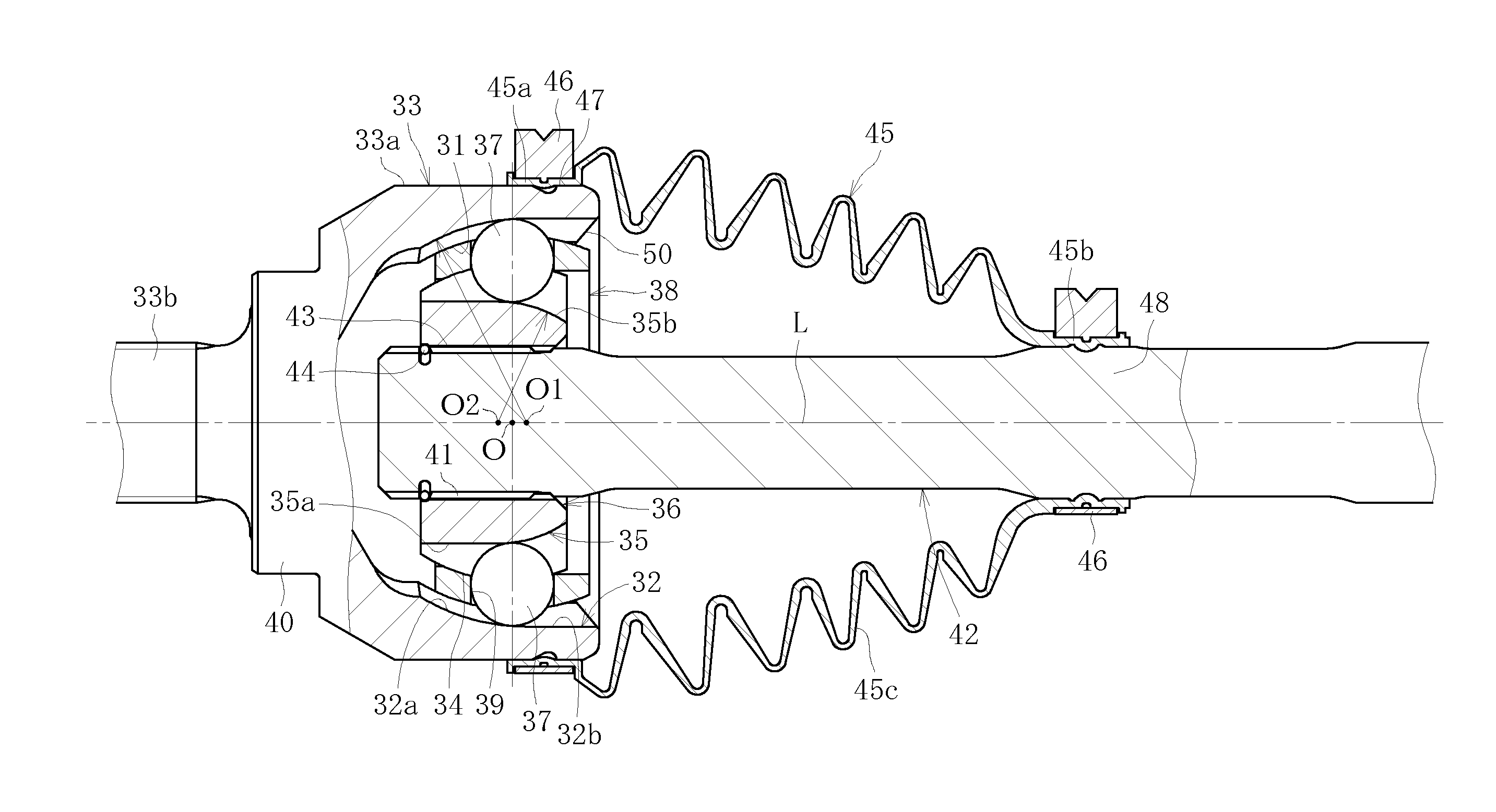
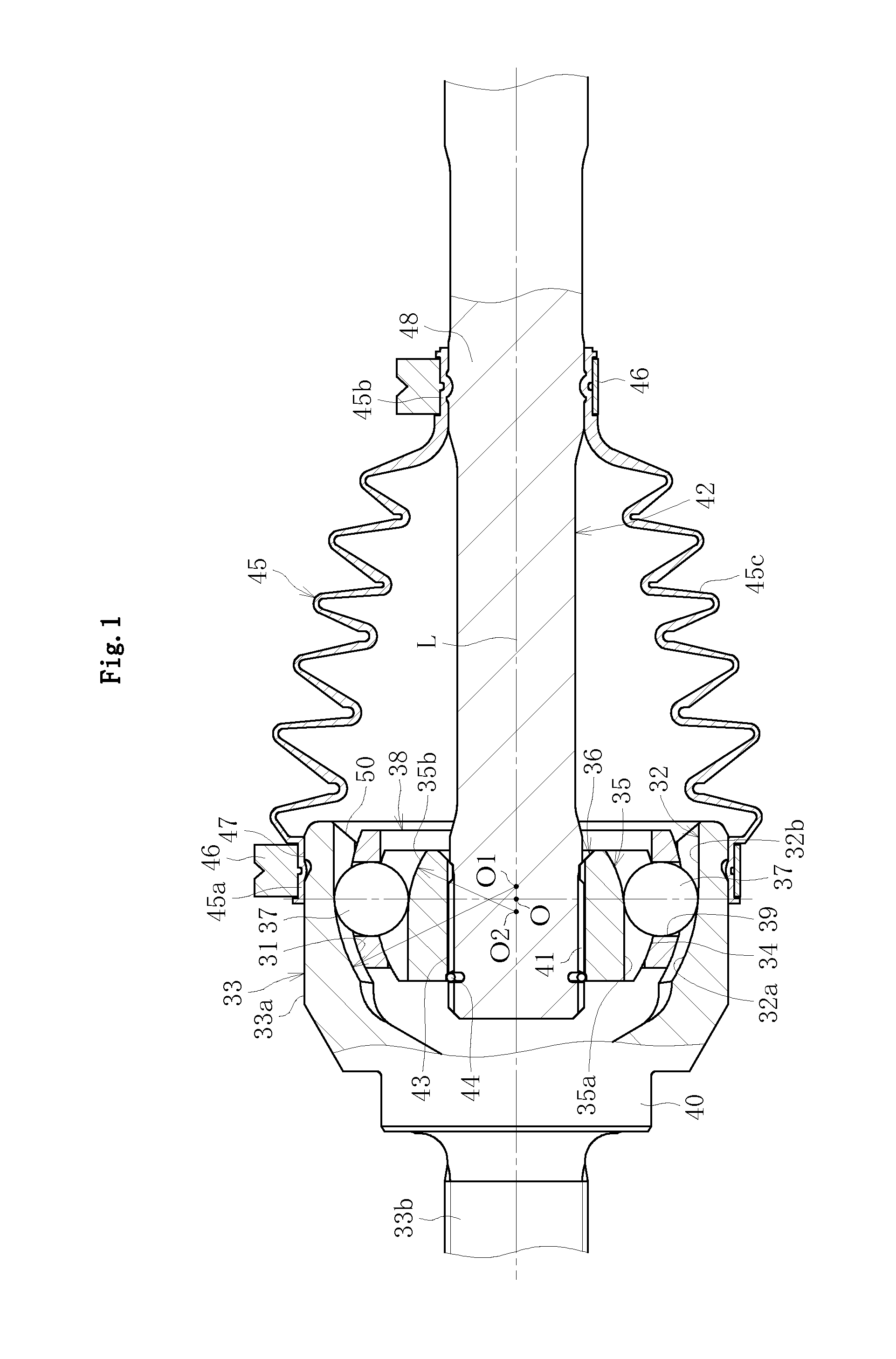
[0081]Next, Example is described. Inventive products 1, 2, 3, and 4 and comparative products 1, 2, and 3 were prepared, and high load durability, low load durability, high angle durability, and transmission efficiency of each of those inventive products and comparative products were examined. Materials for components (outer joint member, inner joint member, cage, and balls) of those inventive products and comparative products are shown in Table 1. Hardnesses after heat treatment of the track grooves 32 of the outer joint member 33, the track grooves 35 of the inner joint member 36, the ball contact surfaces of the window portions 39 of the cage 38, and the balls 37 were respectively HRC 60.1, HRC 61.7, HRC 62.0, and HRC 65.1. Further, after those components were maintained at 200° C. for one hour, reduction in hardness was measured. As a result, the hardnesses of the track grooves 32 of the outer joint member 33, the track grooves 35 of the inner joint member 36, the ball contact su...


PUM


Abstract

Provided is a fixed type constant velocity universal joint which can achieve, at low cost, excellent properties in terms of durability, high load condition, low load condition, and high angle condition. The fixed type constant velocity universal joint comprises a lubricating grease sealed therein. A surface roughness of a ball (37) is set to Ra 0.15 μm or less and a surface roughness of a counterpart surface on which the ball (37) rolls is set to be higher than the surface roughness of the ball (37). An additive composition of the lubricating grease comprises a base oil, a diurea compound, molybdenum dithiocarbamate, zinc dialkyldithiophosphate, melamine cyanurate, molybdenum disulfide, and calcium salt of alkylaromatic sulfonic acid.

Description

TECHNICAL FIELD[0001]The present invention relates to a fixed type constant velocity universal joint which is used, for example, for a drive shaft of a power transmission device for automobiles and industrial machines.BACKGROUND ART[0002]As illustrated in FIG. 5, a fixed type constant velocity universal joint includes an outer joint member 3 having an inner surface 1 provided with a plurality of track grooves 2, an inner joint member 6 having an outer surface 4 provided with a plurality of track grooves 5 paired with the track grooves 2 of the outer joint member 3, a plurality of balls 7 for transmitting torque while being interposed between the track grooves 2 of the outer joint member 3 and the track grooves 5 of the inner joint member 6, and a cage 8 for holding the balls 7 while being interposed between the inner surface 1 of the outer joint member 3 and the outer surface 4 of the inner joint member 6. The cage 8 includes a plurality of window portions 9 for housing the balls 7,...

Claims


Application Information

Patent Timeline
Patent Type & Authority Applications(United States)
IPC IPC(8): F16C1/04
CPCC10M169/06C10M2201/066C10M2219/044C10M2207/401C10M2203/1006C10M141/10F16C1/04F16D2300/12F16D2003/22316C10M2215/1026C10M2215/221C10M2219/046C10M2219/068C10M2223/045C10N2230/06C10N2240/046C10N2250/10F16D3/2237F16D3/2245F16D2003/22309C10N2210/06C10N2210/02F16D2300/10F16D3/223F16D2300/06C10N2030/06C10N2040/046C10N2050/10C10N2010/12C10N2010/04
Inventor YOSHIDA, KAZUHIKOSONE, KEISUKEKOHARA, MIKA
Owner NTN CORP
Learn More