Flamesheet combustor

a combustion system and flame sheet technology, applied in mechanical equipment, machines/engines, lighting and heating apparatus, etc., can solve the problems of preventing any improvement through altering the mixing length, reducing the load turndown, and high emissions of diffusion-type nozzles, so as to reduce polluting emissions, reduce load conditions, and reduce the effect of polluting emissions

Inactive Publication Date: 2005-08-30
H2 IP UK LTD
View PDF25 Cites 98 Cited by
  • Summary
  • Abstract
  • Description
  • Claims
  • Application Information

AI Technical Summary

Benefits of technology

[0008]The present invention discloses a gas turbine combustion system for reducing polluting emissions such as NOx and CO, while being able to provide stable combustion at lower load conditions. The combustion system contains a casing having a center axis, which is in fluid communication with the engine compressor, and an end cover fixed to the casing. In the preferred embodiment, the end cover contains a plurality of first injectors arranged in a first array about the end cover and a plurality of second injectors arranged in a second array about the end cover, with the second array radially outward of the first array. Located proximate the end cover is a first swirler having a plurality of passageways oriented generally perpendicular to the casing center axis for inducing a swirl generally radially inward to a first portion of the compressed air. Fuel, which is injected through the first and second injectors, mixes with the first portion of compressed air from the first swirler before entering a liner through a dome section. Additional fuel is also introduced to a second portion of compressed air through a plurality of third injectors located in a manifold of an aft injector assembly. The third injectors are divided into multiple circumferential sectors to allow for various fuel staging circumferentially around the aft injector assembly. To enhance mixing between fuel from the third injectors and second portion of compressed air, a second swirler is positioned adjacent the aft injector assembly for imparting a swirl to the second portion of compressed air. This fuel and air mixes in a second passage located between a first part of the liner and the dome prior to entering the liner and mixing with the fuel and first portion of compressed air from the first swirler region. Upon entering the liner, the premixture from the second passage must undergo a complete reversal of flow direction that causes strong recirculation zones at the forward end of the liner. These recirculation zones help to increase combustor stability by providing a region where a portion of the hot combustion gases can be entrained and recirculate to provide continuous ignition to the incoming premixed fuel and compressed air. Fuel flow to each of the first, second, and third sets of injectors is controlled independently to allow for fuel staging throughout various load conditions to control NOx and CO emissions at each load setting.

Problems solved by technology

Diffusion type nozzles produce high emissions due to the fact that the fuel and air burn stoichiometrically at high temperature to maintain adequate combustor stability and low combustion dynamics.
However, in this configuration the fuel is injected in relatively the same plane of the combustor, and prevents any possibility of improvement through altering the mixing length.
The amount of load turndown is limited by the decreasing flame temperature as the load is decreased, making the flame unstable to the point where flashback occurs into the first combustion chamber.
Combustion systems of the prior art have been known to become unstable at lower load settings while also producing unacceptable levels of NOx and CO emissions at lower load settings, especially below 50% load.
The combination of potentially unstable combustion and higher emissions often times prevents engine operators from running engines at lower load settings, forcing the engines to either run at higher settings, thereby burning additional fuel, or shutting down, and thereby losing valuable revenue that could be generated from the part-load demand.
A further problem with shutting down the engine, is the additional cycles that are incurred by the engine hardware.
Therefore, incurring additional cycles can reduce hardware life requiring premature repair or replacement at the expense of the engine operator.

Method used


Image

  • Flamesheet combustor
  • Flamesheet combustor
  • Flamesheet combustor

Examples


Embodiment Construction

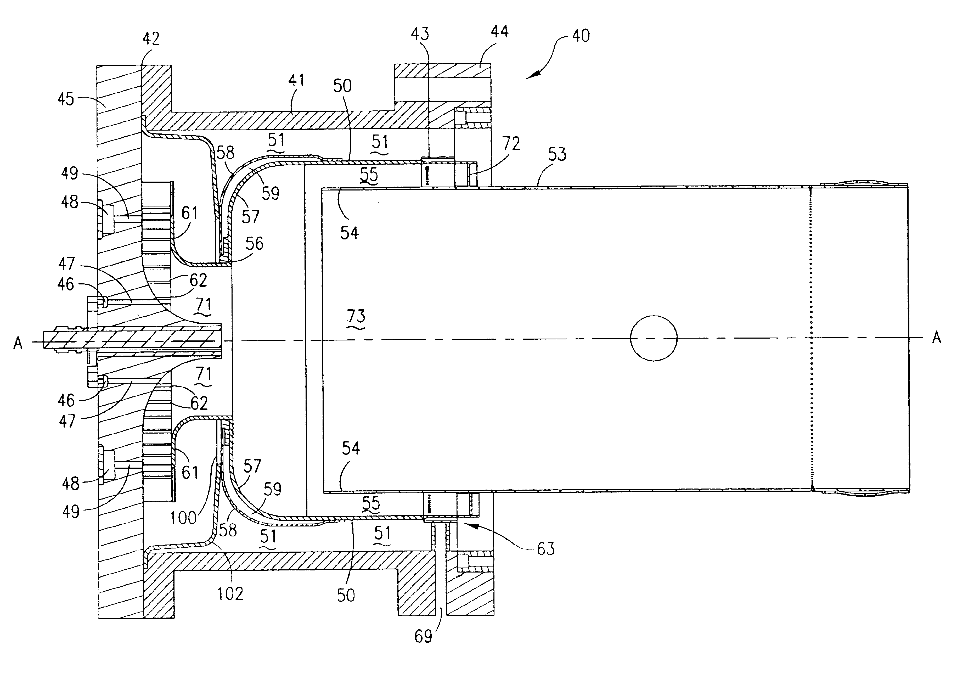
[0021]The preferred embodiment of the present invention will now be described in detail with specific reference to FIGS. 3-8. Referring now to FIGS. 3 and 4, a gas turbine combustion system 40 of the present invention is shown. Combustion system 40 includes a casing 41 having a first end 42, a second end 43, and a center axis A—A. Casing 41, which is mounted to an engine through flange 44, is in fluid communication with compressed air from a compressor.

[0022]Referring now to FIGS. 4 and 5, an end cover 45 is fixed to casing first end 42, with end cover 45 having at least one fuel source in fluid communication with at least one set of injectors. In the preferred embodiment a first fuel source 46 is in fluid communication with a plurality of first injectors 47, where first injectors 47, comprising at least two injectors, are arranged in a first array radially outward of center axis A—A. Furthermore, the preferred embodiment of end cover 45 also contains a second fuel source 48 in flui...


PUM


Abstract

A gas turbine combustion system having reduced emissions and improved flame stability at multiple load conditions is disclosed. The improved combustion system accomplishes this through complete premixing, a plurality of fuel injector locations, combustor geometry, and precise three dimensional staging between fuel injectors. Axial, radial, and circumferential fuel staging is utilized including fuel injection proximate air swirlers. Furthermore, strong recirculation zones are established proximate the introduction of fuel and air premixture from different stages to the combustion zone. The combination of the strong recirculation zones, efficient premixing, and staged fuel flow thereby provide the opportunity to produce low emissions combustion at various load conditions.

Description

BACKGROUND OF THE INVENTION[0001]1. Field of the Invention[0002]This invention relates in general to gas turbine combustion systems and specifically to a gas turbine combustion system that can operate at significantly lower load conditions while having stable combustion and lower emissions.[0003]2. Description of Related Art[0004]In an effort to reduce the amount of pollution emissions from gas-powered turbines, governmental agencies have enacted numerous regulations requiring reductions in the amount of oxides of nitrogen (NOx) and carbon monoxide (CO). Lower combustion emissions can often be attributed to a more efficient combustion process, with specific regard to fuel injector location and mixing effectiveness.[0005]Early combustion systems utilized diffusion type nozzles, where fuel is mixed with air external to the fuel nozzle by diffusion, proximate the flame zone. Diffusion type nozzles produce high emissions due to the fact that the fuel and air burn stoichiometrically at h...

Claims


Application Information

Patent Timeline
Patent Type & Authority Patents(United States)
IPC IPC(8): F23R3/14F23R3/28F23R3/04F23R3/34
CPCF23R3/14F23R3/286F23R3/34
Inventor STUTTAFORD, PETER J.JENNINGS, STEPHENGREEN, ANDREWMCMAHON, RYANCHEN, YANRIZKALLA, HANYCARELLA, JOHNDURAIBABU, VAMSISPALDING, MARTIN
Owner H2 IP UK LTD
Why Eureka
Try Eureka