Signal separation device

a signal separation and signal technology, applied in the field of signal separation devices, can solve the problems of degrading the isolation characteristics of the transmission filter and the reception filter in some cases, and the difficulty of reducing the size of the signal separation device, and achieve the effect of enhancing the isolation characteristics of the high-frequency side passband

Active Publication Date: 2014-07-17
MURATA MFG CO LTD
View PDF2 Cites 14 Cited by
  • Summary
  • Abstract
  • Description
  • Claims
  • Application Information

AI Technical Summary

Benefits of technology

[0020]According to various preferred embodiments of the present invention, in a signal separation device including a first passband and a second passband adjacent to each other, isolation characteristics in a high-frequency-side passband are enhanced.

Problems solved by technology

As a result, there may be a case in which it is difficult to reduce the size of the signal separation device.
However, when the passband of the transmission filter and the passband of the reception filter are close to each other, the isolation characteristics between the transmission filter and the reception filter are degraded in some cases.

Method used


Image

  • Signal separation device
  • Signal separation device
  • Signal separation device

Examples


Embodiment Construction

[0029]Hereinafter, preferred embodiments of the present invention will be described. Note that identical elements or equivalent elements are denoted by the same reference symbols and duplicated descriptions thereof may be omitted in some cases.

[0030]Note that in the preferred embodiments described below, when quantities or amounts are described, the scope of the present invention is not limited by these quantities or amounts, unless specifically described. Further, in the preferred embodiments described below, components of a configuration are not necessarily essential to the present invention unless specifically described.

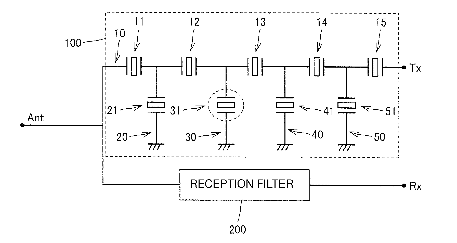
[0031]FIG. 1 is a schematic circuit diagram of a signal separation device according to a preferred embodiment of the present invention. The signal separation device according to the present preferred embodiment may preferably be mounted in, for example, a high-frequency device such as a cellular phone supporting a code division multiple access (CDMA) system such a...


PUM


Abstract

A signal separation device is a duplexer in which a reception frequency band is located at higher frequencies than a transmission frequency band. A series arm of a ladder transmission filter includes a plurality of series arm resonators, and parallel arms respectively include parallel arm resonators. The parallel arm resonators include the parallel arm resonators having resonant frequencies lower than those of the series arm resonators and the parallel arm resonator that has a resonant frequency which is located within the reception frequency band and which is higher than the resonant frequency of the series arm resonators and that has a lower capacitance than the series arm resonators and the parallel arm resonators.

Description

BACKGROUND OF THE INVENTION[0001]1. Field of the Invention[0002]The present invention relates to signal separation devices, and specifically relates to signal separation devices including a first passband and a second passband adjacent to each other.[0003]2. Description of the Related Art Japanese Unexamined Patent Application Publication No. 2008-271230 discloses a signal separation device that includes a transmission filter and a reception filter connected to an antenna and that has a configuration in which a ground potential connected to the reception filter is isolated from other ground potentials.[0004]Japanese Unexamined Patent Application Publication No. 2010-109894 discloses a ladder-type signal separation device that has a transmission filter and a reception filter and that has a configuration in which a single parallel-arm resonator is used as a notch filter, thereby suppressing a sub-resonant response in the sub-resonant frequency band of the transmission filter or recept...

Claims


Application Information

Patent Timeline
Patent Type & Authority Applications(United States)
IPC IPC(8): H03H9/64H03H9/02
CPCH03H9/02535H03H9/64H01L2224/16225H01L2924/181H03H9/0542H03H9/0576H03H9/059H03H9/6483H03H9/725H01L2924/00012H03H9/706
Inventor UESAKA, KENICHI
Owner MURATA MFG CO LTD
Why Eureka
Try Eureka