
Backpressure control unit, liquid ejecting head, and liquid ejecting apparatus

a control unit and liquid ejector technology, applied in printing, other printing apparatus, etc., to achieve the effect of high-quality printed materials

Active Publication Date: 2014-07-17
SEIKO EPSON CORP
View PDF9 Cites 7 Cited by
  • Summary
  • Abstract
  • Description
  • Claims
  • Application Information

AI Technical Summary

Benefits of technology

The invention provides a backpressure control unit, a liquid ejecting head, and a liquid ejecting apparatus that improve yields by absorbing discrepancies in the properties of backpressure control valves to the greatest extent possible while making it possible to change designs in a flexible manner. The flow channel member is divided into multiple blocks, which makes it easy to adjust the discrepancies in the properties of the backpressure control valve by changing the combinations of the flow channel member. The flow channel members and the base portion are connected by applying pressure in a direction that intersects with the surfaces of connection, which ensures a favorable sealed state at the linking portion between the flow channel member and the base portion. This invention allows for better backpressure control and results in high quality printed materials.

Problems solved by technology

As described above, with the flow channel member according to JP-A-2005-186344, a plurality of rows are integrated and housed within the cover, and thus there is a problem, particularly when multiple colors of ink are used, where there are discrepancies among the properties of the backpressure control valves in each valve unit caused by warping and the like in the overall apparatus, including the cover.
It should be noted that these problems are not limited to ink jet recording heads, and are also present in other liquid ejecting heads that eject liquids aside from ink.

Method used


Image

  • Backpressure control unit, liquid ejecting head, and liquid ejecting apparatus
  • Backpressure control unit, liquid ejecting head, and liquid ejecting apparatus
  • Backpressure control unit, liquid ejecting head, and liquid ejecting apparatus

Examples


first embodiment

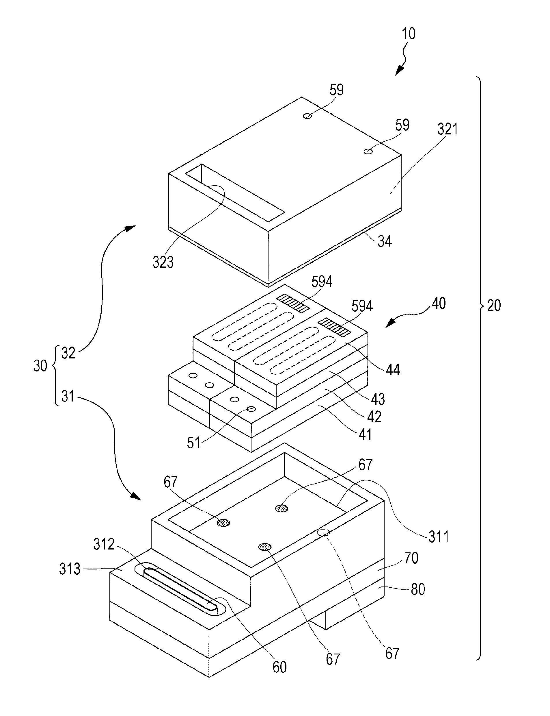
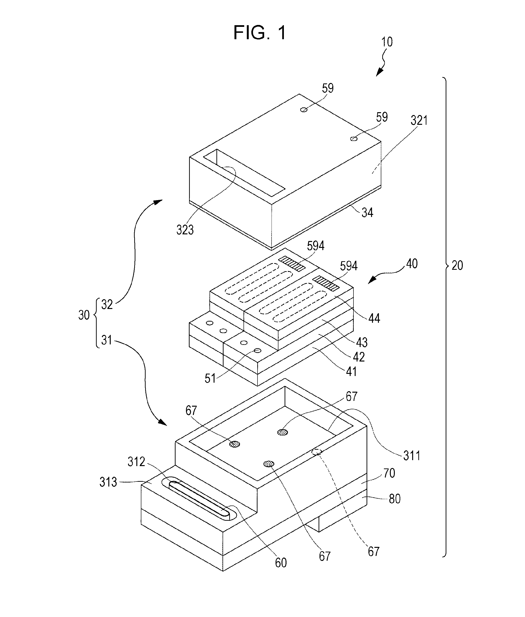
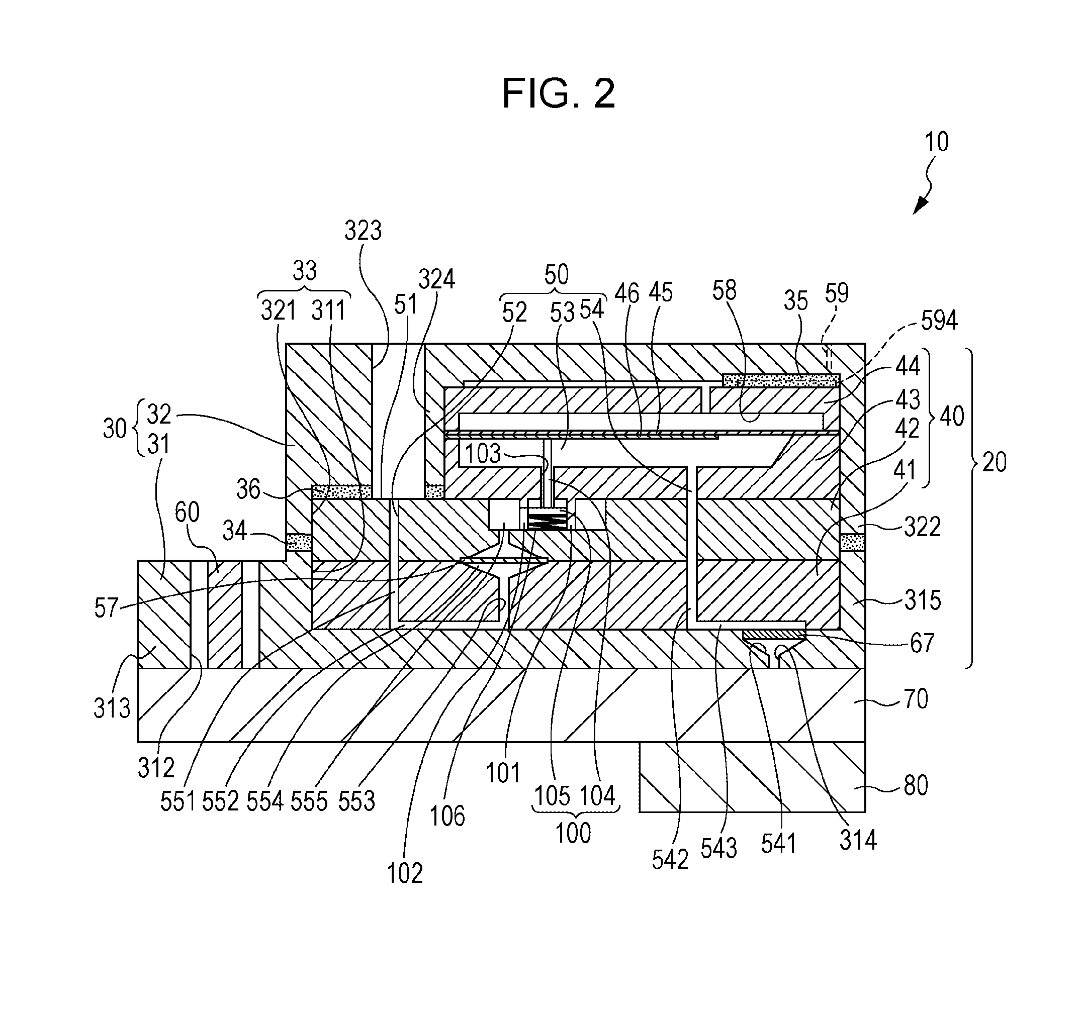
[0025]FIG. 1 is an exploded perspective view of an ink jet recording head serving as an example of a liquid ejecting head according to a first embodiment of the invention, whereas FIG. 2 is a cross-sectional view illustrating the same.

[0026]As illustrated in FIGS. 1 and 2, an ink jet recording head (also called simply a “recording head”) 10 serving as an example of the liquid ejecting head according to the first embodiment of the invention includes a backpressure control unit 20, a circuit board 60 provided in a base area of the backpressure control unit 20, a head case 70 provided below the backpressure control unit 20, and a plurality of main head units 80 anchored to the head case 70.

[0027]The backpressure control unit 20 supplies ink from a liquid holding unit (not shown) such as an external ink tank that holds ink, to the main head units 80.

[0028]Here, the backpressure control unit 20 will be described in detail. The backpressure control unit 20 includes a cover 30 configured o...

second embodiment

[0063]FIG. 3 is an exploded perspective view of an ink jet recording head serving as an example of a liquid ejecting head according to a second embodiment of the invention, whereas FIG. 4 is a cross-sectional view illustrating the same.

[0064]As illustrated in FIGS. 3 and 4, a recording head according to the second embodiment of the invention includes a backpressure control unit 120, the circuit board 60 provided in a base area of the backpressure control unit 120, the head case 70 provided below the backpressure control unit 120, and the plurality of main head units 80 anchored to the head case 70, in the same manner as in the first embodiment.

[0065]Here, the backpressure control unit 120 according to this embodiment includes a cover 130 configured of a hollow box-shaped member, and a flow channel member 140 serving as a valve unit provided within the cover 130.

[0066]The cover 130 is divided vertically into a base portion 131 and the cover portion 32. The flow channel member 140 is ...


PUM


Abstract

A backpressure control unit that introduces a liquid from an external liquid holding unit and supplies the liquid to a main head unit for ejecting the liquid via a nozzle opening includes a flow channel member having an introduction channel, a valve member, and a supply channel, and a cover that that combines a base portion and a cover portion and houses the flow channel member therewithin. This provides a backpressure control unit that improves yields by absorbing discrepancies in properties of backpressure control valves to the greatest extent possible while at the same time making it possible to change designs in a flexible manner.

Description

BACKGROUND[0001]1. Technical Field[0002]The present invention relates to backpressure control units for supplying a liquid to a main head unit of a liquid ejecting head that ejects the liquid from nozzle openings, and furthermore relates to liquid ejecting heads and liquid ejecting apparatuses that include such backpressure control units; the invention is particularly useful when applied in a backpressure control unit having a flow channel member.[0003]2. Related Art[0004]An ink jet recording head, which is an example of a liquid ejecting head, prints onto a medium such as paper by instigating pressure changes in pressure generation chambers that communicate with nozzle openings and ejecting ink droplets from the nozzle openings onto the medium. Providing a flow channel member, for supplying ink to a main head unit having the nozzle openings, in a valve unit (a backpressure control unit) has been proposed as an example of this type of ink jet recording head (see JP-A-2005-186344, fo...

Claims


Application Information

Patent Timeline
IPC IPC(8): B41J2/175
CPCB41J2/175B41J2/17556
Inventor MIYAJIMA, HIROKI
Owner SEIKO EPSON CORP
Learn More