Deployment shelter

a technology for deploying shelters and end panels, applied in the direction of transportation and packaging, transportation items, transportation vehicles, etc., can solve the problems of reducing the shielding performance of internal space, the inability to provide movable end panels, and the inability to deploy movable panels smoothly. to achieve the effect of smooth opening and closing

Inactive Publication Date: 2014-07-24
NIPPON TREX
View PDF26 Cites 38 Cited by
  • Summary
  • Abstract
  • Description
  • Claims
  • Application Information

AI Technical Summary

Benefits of technology

[0009]Additionally, in the deployed state, since the hinge between the movable roof panel and the movable side panel, the hinge between the movable roof panel and the main body side roof panel, and the hinge between the longitudinal beam member and the main body side roof panel are exposed to the outside on the upper side of the shelter, each hinge portion is reduced in sealing performance, so that rain water may enter the internal space in the rain.
[0010]An object of the present invention is to provide a deployment shelter in which a plurality of movable panels can be driven smoothly between their stored states and their deployed states.
[0011]Another object of the present invention is to provide a deployment shelter having an internal space improved in water-tightness.
[0013]Since the movable roof panels, the movable floor panels, and the movable side panels are automatically pivoted by the actuators, respectively, it is easy to perform a switching operation of the movable panels of the deployment shelter between the deployed states and the stored states. Since the movable roof panels, the movable floor panels, and the movable side panels are individually driven by respective actuators, it is possible to drive the actuators to smoothly open and close these movable panels.
[0014]Since the hinges coupling the movable panels are not exposed to rain water, rain water can be prevented from entering the internal space of the shelter from the hinges.

Problems solved by technology

Therefore, the three movable panels are deployed while being changed in pivotal center, so that the movable panels cannot be deployed smoothly.
The shelter is provided with flexible sheets for covering both end portions of the expanded internal space, but since the internal space is covered with the sheets, the shielding performance of the internal space is reduced.
A shelter of this type cannot be provided with a movable end panel, because it is necessary to prevent the movable end panel from strongly contacting with the three movable panels.
If this shelter is modified so that the movable end panel is deployed without contacting with the three deployed movable panels, sealing performance between the deployed movable end panel and the three movable panels may be deteriorated.
Additionally, in the deployed state, since the hinge between the movable roof panel and the movable side panel, the hinge between the movable roof panel and the main body side roof panel, and the hinge between the longitudinal beam member and the main body side roof panel are exposed to the outside on the upper side of the shelter, each hinge portion is reduced in sealing performance, so that rain water may enter the internal space in the rain.

Method used


Image

  • Deployment shelter
  • Deployment shelter
  • Deployment shelter

Examples


Embodiment Construction

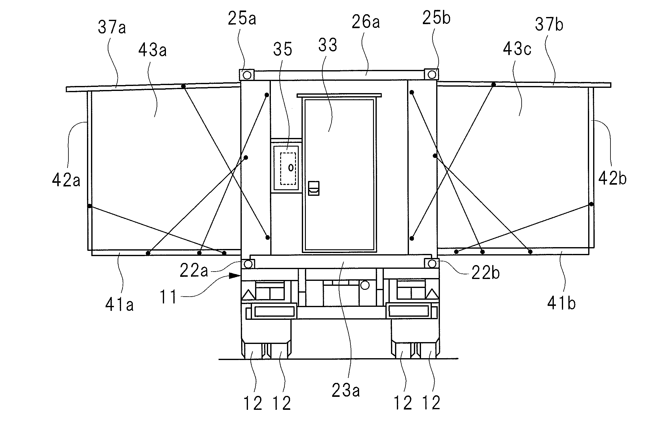
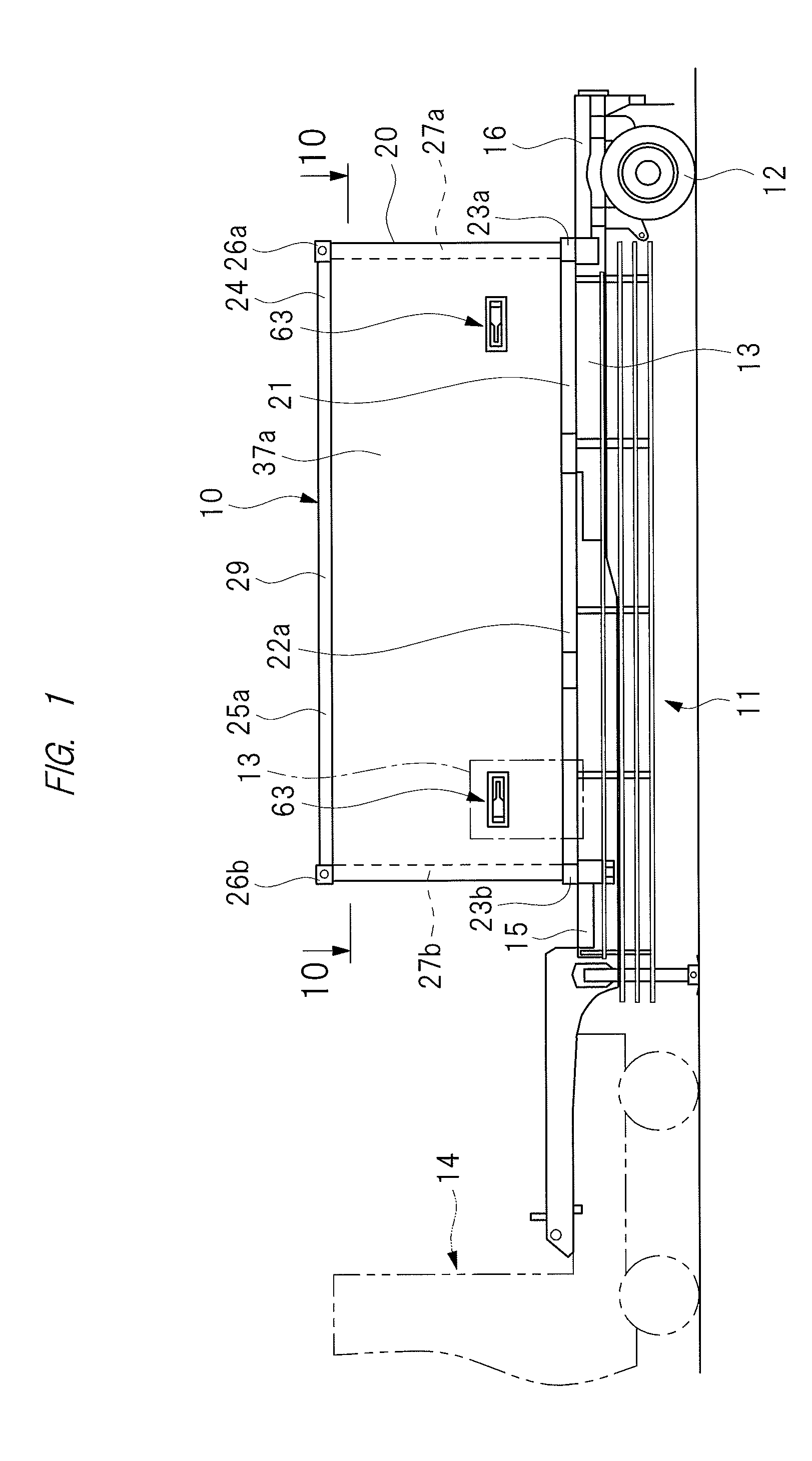
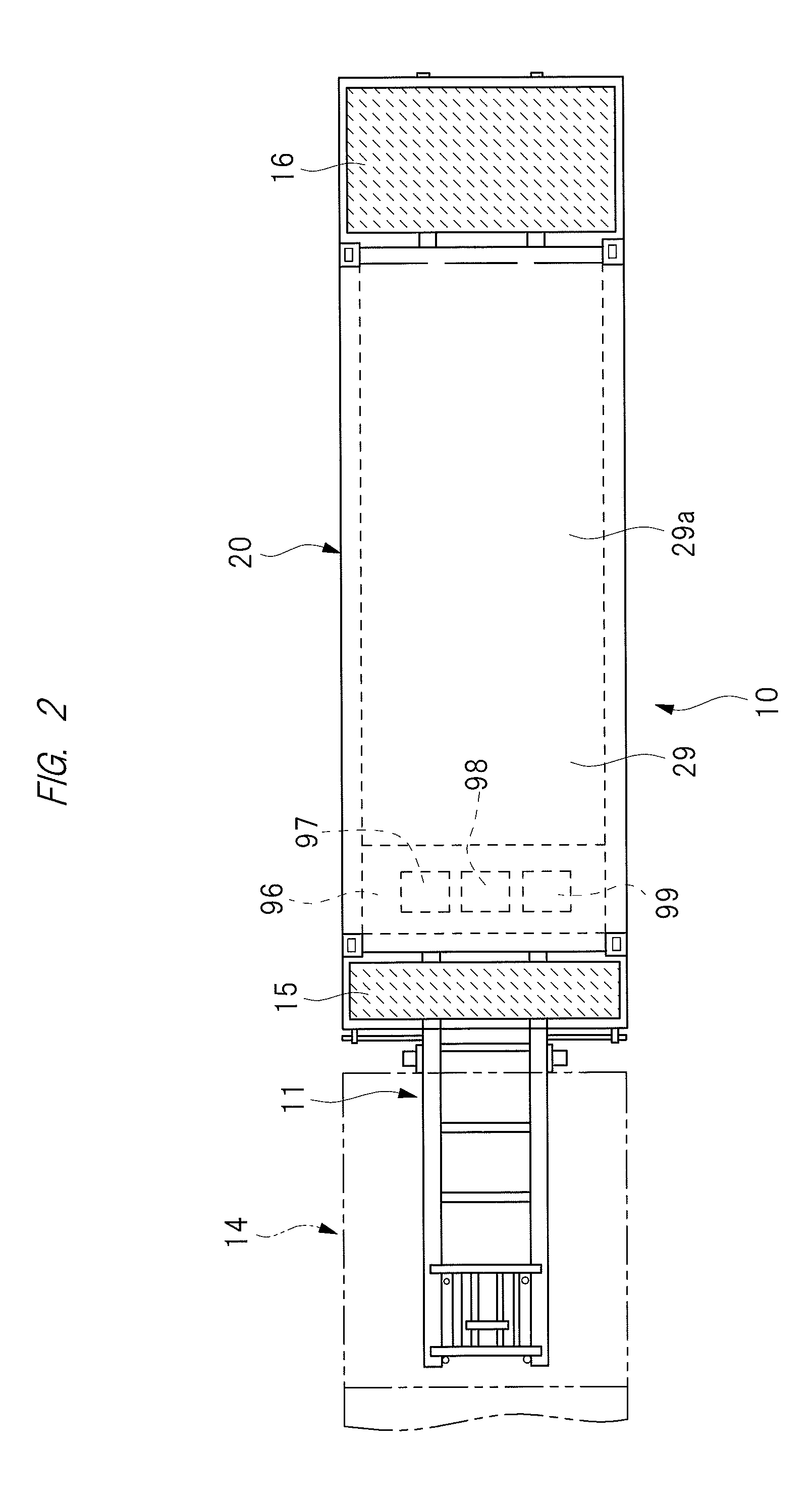
[0047]Hereinafter, embodiments of the present invention will be described in detail with reference to the drawings. As shown in FIGS. 1 to 5, a deployment shelter 10 can be installed on a trailer 11. In this specification, the term “deployment shelter 10” is hereinafter simply referred to as “shelter 10”. The trailer 11 has a luggage carrier 13 having wheels 12, and a tractor 14 for pulling the luggage carrier 13.

[0048]The shelter 10 can be loaded on and unloaded from the luggage carrier 13. The shelter 10 is switchable between its deployed state and its stored state, and has a rectangular parallelepiped shape in the stored state. The shelter 10 is set to have dimensions similar to those of a general-purpose container to be loaded on the luggage carrier 13, and specifications required as the general-purpose container. Specifically, the shelter 10 in the stored state is the same as the general-purpose container in length, width, and height. A deck plate 15 is mounted on the front sid...


PUM


Abstract

An object of the present invention is to provide a deployment shelter which can be changed between a stored state and a deployed state by smoothly driving movable panels. The deployment shelter 10 has a shelter main body 20 in which a floor panel 28 is coupled to a roof panel 29 via four poles. Movable roof panels 37a and 37b which are pivoted between stored positions and deployed positions are respectively attached to side portions of the roof panel 29, movable floor panels 41a and 41b which are pivoted between stored positions and deployed positions are respectively attached to side portions of the floor panel 28. Movable side panels 42a and 42b are respectively attached to the movable floor panels 41a and 41b. Movable end panels 43a and 43b which are pivoted between stored positions and deployed positions are respectively attached to poles. The movable roof panels, the movable floor panels, and the movable side panels are respectively driven by actuators so that they are opened and closed.

Description

CROSS-REFERENCE TO RELATED APPLICATION[0001]The present application is a continuation-in-part of U.S. patent application Ser. No. 13 / 800,083 filed on Mar. 13, 2013, which claims priority under 35 U.S.C. §119 to Japanese Patent Application No. 2013-7652 filed on Jan. 18, 2013, the contents of which are hereby incorporated by reference into this application. The present application also claims priority under 35 U.S.C. §119 to Japanese Patent Application No. 2013-170631 filed on Aug. 20, 2013, the content of which is hereby incorporated by reference into this application.TECHNICAL FIELD OF THE INVENTION[0002]The present invention relates to a deployment shelter which can be changed in shape between a stored state and a deployed state.BACKGROUND OF THE INVENTION[0003]A shelter which can be conveyed by transportation means such as trailer, railroad or boats and ships, and which can be temporarily or continuously used has been developed. A transportable shelter has a rectangular parallele...

Claims


Application Information

Patent Timeline
Patent Type & Authority Applications(United States)
IPC IPC(8): E04B1/344
CPCE04B1/344B60P3/34E04B1/3444E04B1/3442E04B1/343E04H3/28E04H15/48B60P3/00
Inventor NAKAJIMA, MASAYASUZUKI, JUNYAMORIOKA, NOBUYUKI
Owner NIPPON TREX
Why Eureka
Try Eureka