Method of characterizing the sensitivity of an electronic component subjected to irradiation conditions

a technology of sensitivity and electronic components, applied in the field of electronic components, can solve the problems of parasitic current creation in the component, the application executed by the component, the device, and the application using it, and the malfunction of temporarily or permanently, etc., to reduce the cost of characterization, easy to model, and increase flexibility

Inactive Publication Date: 2014-07-24
EURON AERONAUTIC DEFENCE & SPACE
View PDF4 Cites 8 Cited by
  • Summary
  • Abstract
  • Description
  • Claims
  • Application Information

AI Technical Summary

Benefits of technology

[0032]To increase flexibility and greatly reduce the cost of this characterization, the present method for characterizing the sensitivity of a component to radiation combines experimental characterization using an ionizing radiation source having limited properties (especially regarding energy range) with a simulating code.
[0033]An additional advantage of this type of ionizing radiation source is that its properties and geometric radiation configuration (energy spectrum, flux, etc.) are perfectly known and therefore easily modeled with a simulating tool.
[0034]As regards the simulating code used to calculate the sensitivity of a component under a number of radiation conditions, it requires a limited number of input parameters to calculate, for a radiation environment, the probability that radiation-related effects (typically a failure of preset type) will occur. It may either be an analytical method (such as, for example, a BGR, SIMPA or PROFIT method) or a Monte-Carlo type approach. In order to predict the sensitivity of a component to radiation, Monte-Carlo approaches simulate a large number of incident particles and study the response of the component to each event individually. This type of approach allows statistical data to be gathered and an average response to be obtained for the component.

Problems solved by technology

These errors may cause an application executed by the component to malfunction.
One of the consequences of these stresses is the creation of parasitic currents in the component.
Depending on the location of the interactions between the material of the component and the incident particles, and depending on the operating conditions of the component, these interactions may have various effects, and may lead the device, and the application using it, to malfunction temporarily or permanently.
However, this type of test is very expensive because exhaustive characterization requires substantial beam time.
Moreover, the availability of most of these machines is relatively limited because they are few in number and subject to very high demand.

Method used


Image

  • Method of characterizing the sensitivity of an electronic component subjected to irradiation conditions
  • Method of characterizing the sensitivity of an electronic component subjected to irradiation conditions
  • Method of characterizing the sensitivity of an electronic component subjected to irradiation conditions

Examples


Embodiment Construction

[0057]In the rest of the description the particular case of an electronic memory component, comprising an array of elementary cells capable of adopting a plurality of logic states depending on their electronic charge, will be considered. However, the method described here more generally applies to any type of component or piece of electronic equipment.

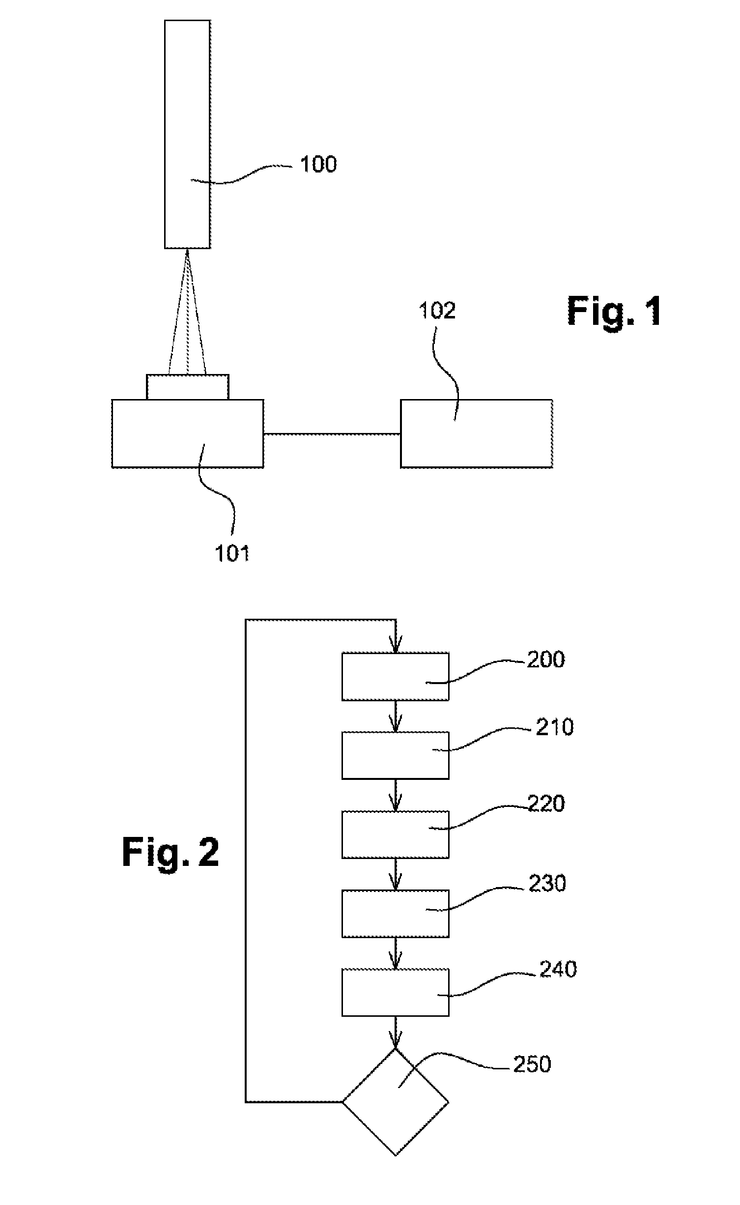
[0058]The method for selecting electronic components depending on their sensitivity to ionizing radiation implements various elements that are illustrated in FIG. 1.

[0059]Firstly, a radioactive source 100 of a type known per se is used, said source 100 being installed on a supporting structure (not shown in the figure) that is intended to receive a piece of electronic equipment or a component 101 placed a distance h from the source and according to a preset geometry.

[0060]The method also employs means 102 for measuring various signals of interest that originate from the component 101 when the latter is irradiated by the source 100. The...


PUM


Abstract

A method of selecting a piece of electronic equipment subjected to irradiation conditions comprising at least one electronic component by characterizing a sensitivity parameter of the electronic component to the irradiation conditions listed in a predetermined specifications. The electronic component is irradiated with a source of ionizing radiation having the known irradiation characteristics and geometry. A set of operating values of the electronic component are measured during the irradiation of the electronic component. The sensitivity of the electronic component are measured for a number of irradiation conditions lower than all of the conditions listed in the specifications. The measured results are extrapolated to the other irradiation conditions of the specifications.

Description

[0001]The present invention relates to the field of devices and methods for controlling the quality of electronics. It in particular relates to a method for characterizing the sensitivity of a component or a piece of electronic equipment subjected to ionizing radiation such as that present in the natural radiation environment. The invention employs an ionizing radiation source and a predicting tool.INTRODUCTION AND PRIOR ART[0002]Electronic components, especially complex components and power components, are more and more commonly used in hostile environments, and in particular in environments that subject them to various stresses (due to cosmic radiation, electromagnetic radiation, etc.), especially when used on-board aircraft or satellites. It is therefore desirable to know, for the sake of operational safety, their sensitivity to these stresses, this sensitivity then being defined as the probability of a single error, simultaneous errors, or even destructive failure occurring. The...

Claims


Application Information

Patent Timeline
Patent Type & Authority Applications(United States)
IPC IPC(8): G01R31/26
CPCG01R31/2601G01R31/31816G01R31/002G01R31/2881G01R31/30G01R31/008
Inventor MILLER, FLORENTWEULERSSE, CECILE
Owner EURON AERONAUTIC DEFENCE & SPACE
Why Eureka
Try Eureka