Delay locked loop and method of generating clock

Active Publication Date: 2014-07-24
IND ACADEMIC COOP FOUNDATION YONSEI UNIV
View PDF14 Cites 19 Cited by
  • Summary
  • Abstract
  • Description
  • Claims
  • Application Information

AI Technical Summary

Benefits of technology

[0011]The present invention provides a delay locked loop that has a compact size, achieves low

Problems solved by technology

However, when controlling each delay line by using the same control code, it is difficult to obtain accurate phase shift due to a mismatch between delay lines and there is a limitation in that a phase shift error occurs.
However, since a controller must exist for each delay line independently, such a DLL has a limitation in that design complexity increases.
Also, there are limitations in that a plurality of delay lines is needed and an area and power consumption increase.
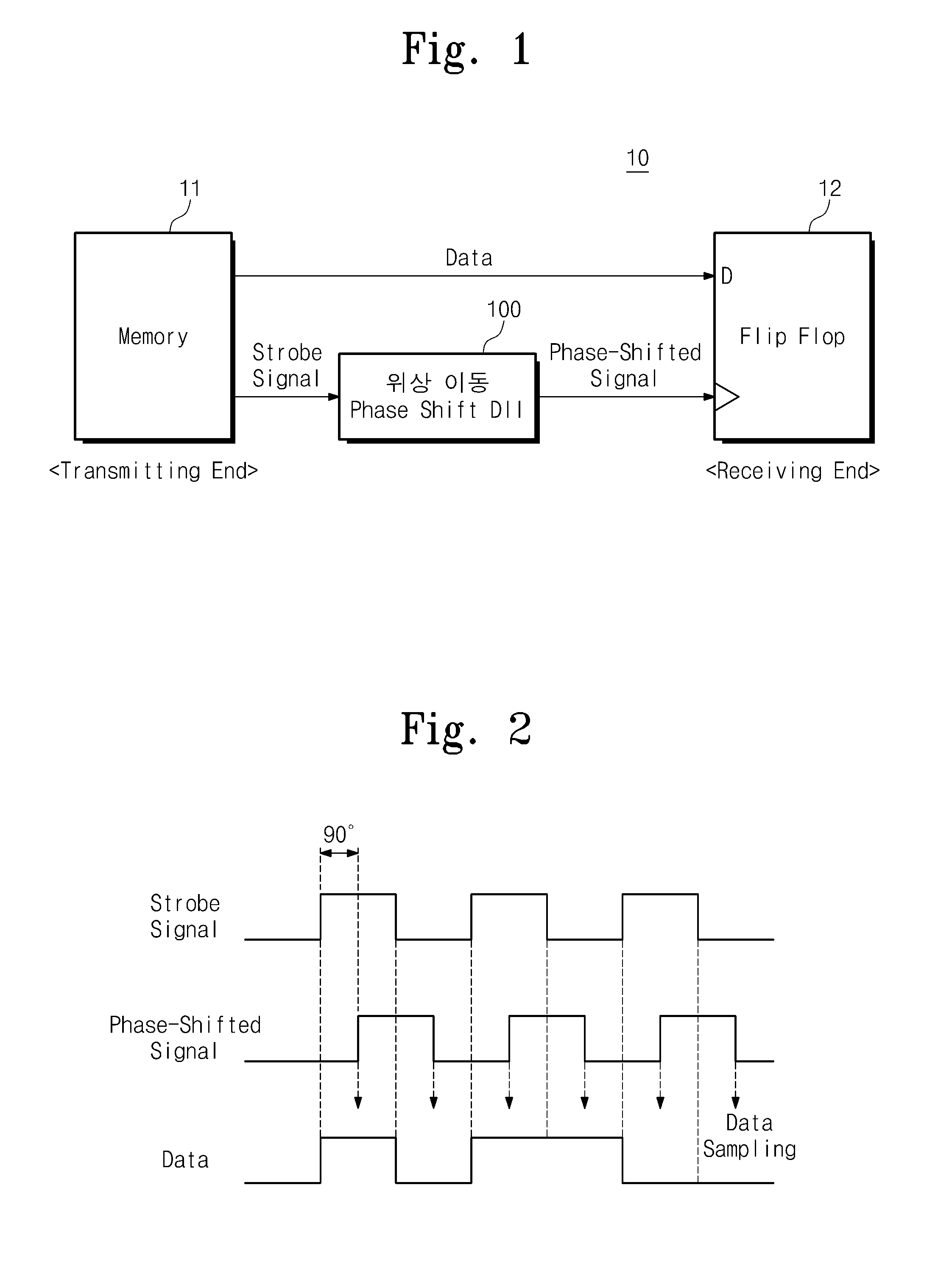
When data is sampled by using an output clock of the duty cycle departs from 50%, a timing margin decreases and a bandwidth decreases, so it may be difficult to perform data sampling at an accurate timing.
However, due to factors such as a characteristic of an external jitter and non-uniform delay values of internal delay elements, the duty cycle of the output clock

Method used


Image

  • Delay locked loop and method of generating clock
  • Delay locked loop and method of generating clock
  • Delay locked loop and method of generating clock

Examples


Example

[0047]Other advantages and features of the present invention, and implementation methods thereof will be clarified through following embodiments described with reference to the accompanying drawings. The present invention may, however, be embodied in different forms and should not be construed as limited to the embodiments set forth herein. Rather, these embodiments are provided so that this disclosure will be thorough and complete, and will fully convey the scope of the present invention to those skilled in the art. Further, the present invention is only defined by scopes of claims. When some terms are not defined, all the terms used herein (including technology or science terms) have the same meanings as those generally accepted by typical technologies in the related art to which the present invention pertains. The terms defined in general dictionaries may be construed as having the same meanings as those used in the disclosure and / or the related art and even when some terms are n...


PUM


Abstract

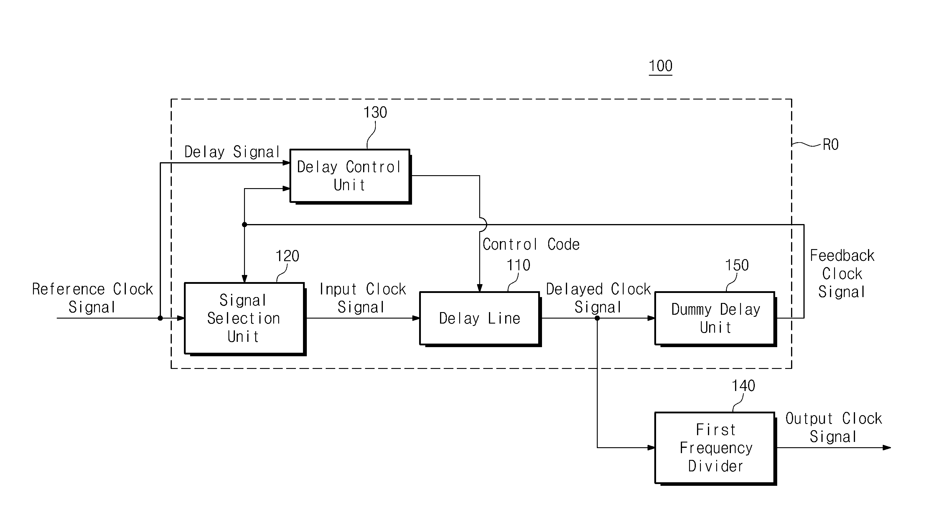
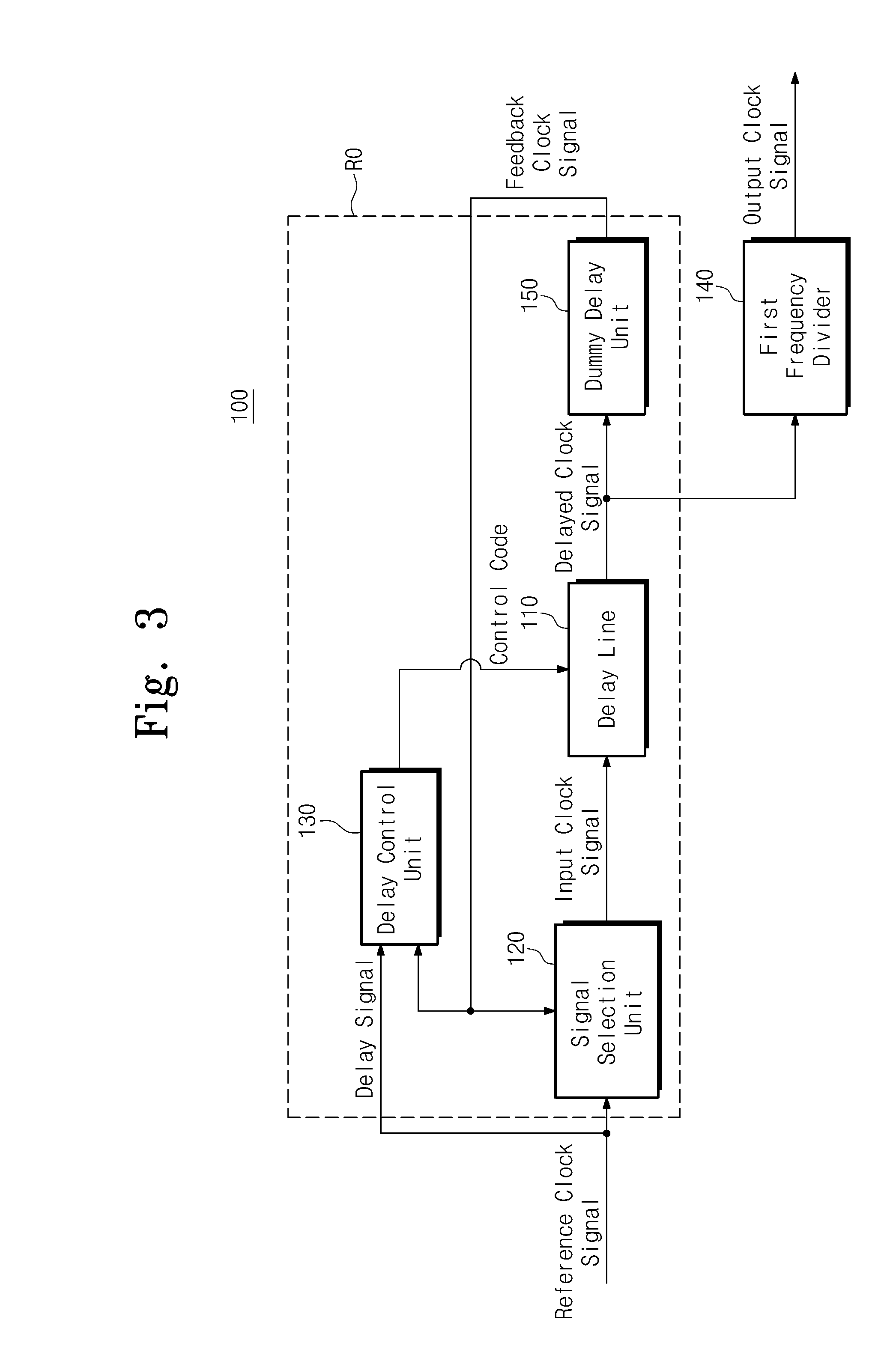
Provided is a delay locked loop (DLL) including a ring oscillator (RO) including a delay line to delay a reference clock signal and generate a delayed clock signal, wherein the RO circulates, through the delay line, a feedback clock signal corresponding to the delayed clock signal to synchronize N cycles of the feedback clock signal with a cycle of the reference clock signal (where N is an integer number equal to or larger than 2); and a first frequency divider dividing the frequency of the delayed clock signal by 1/N (where N is an integer number equal to or larger than 2) to generate an output clock signal.

Description

CROSS-REFERENCE TO RELATED APPLICATIONS[0001]This U.S. non-provisional patent application claims priority under 35 U.S.C. §119 of Korean Patent Application No. 10-2013-0006032, filed on Jan. 18, 2013, the entire contents of which are hereby incorporated by reference.BACKGROUND OF THE INVENTION[0002]The present invention disclosed herein relates to a delay locked loop and method of generating a clock, and more particularly, to a delay locked loop that shifts the phase of a reference clock signal or corrects a duty cycle, and to a method of generating a clock phase-shifted from the reference clock signal or having a corrected duty cycle.[0003]A delay locked loop (DLL) performs an operation of synchronizing the phase of an output clock with a reference clock. In general, the DLL may be used to generate an output clock phase-synchronized with the reference clock in an electronic device such as a semiconductor memory. A DLL circuit may be used for generating a timing signal for the opera...

Claims


Application Information

Patent Timeline
IPC IPC(8): H03L7/08
CPCH03L7/0802H03L7/0814H03L7/0816H03L7/0818H03L7/087H03L7/0995H03L7/16G11C7/22G11C8/00
Inventor JUNG, SEONG-OOKJUNG, DONG-HOONRYU, KYUNGHOPARK, JUNG-HYUN
Owner IND ACADEMIC COOP FOUNDATION YONSEI UNIV
Why Eureka
Try Eureka