Imaging lens and imaging apparatus

a technology of imaging lens and imaging apparatus, which is applied in the direction of optics, instruments, optics, etc., can solve the problems of increasing cost, increasing cost, and unable to produce the lens system at low cost, and achieves the effects of low cost, wide angle of view, and small siz

Active Publication Date: 2014-07-24
JIANGXI OFILM OPTICAL CO LTD
View PDF0 Cites 20 Cited by
  • Summary
  • Abstract
  • Description
  • Claims
  • Application Information

AI Technical Summary

Benefits of technology

[0030]According to the imaging lens in the first aspect of the present invention, the arrangement of refractive power in the entire system, the shapes of the surfaces of the second lens and the third lens, and the like are appropriately set in the lens system including at least six lenses. Therefore, it is possible to achieve small size, low cost, and a wide angle of view. Further, it is possible to realize an imaging lens having high optical performance in which various aberrations are excellently corrected, and an excellent image is obtainable even in a peripheral portion of an image formation area.
[0031]According to the imaging lens in the second aspect of the present invention, the arrangement of refractive power in the entire system, the shapes of the surfaces of the third lens and the like are appropriately set in the lens system including at least six lenses. Therefore, it is possible to achieve small size, low cost, and a wide angle of view. Further, it is possible to realize an imaging lens having high optical performance in which vari

Problems solved by technology

Meanwhile, requirements for an imaging lens to be mounted on an in-vehicle camera, a surveillance camera or the like have become tougher every year.
However, special cementing mate

Method used


Image

  • Imaging lens and imaging apparatus
  • Imaging lens and imaging apparatus
  • Imaging lens and imaging apparatus

Examples


first embodiment

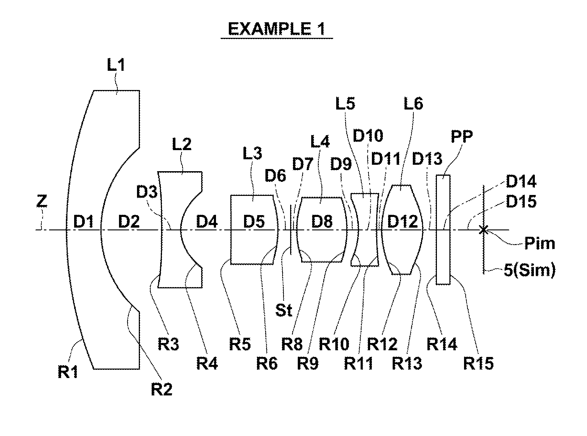
[0082]Further, in the imaging lens the object-side surface of second lens L2 is concave and the object-side surface of third lens L3 is concave. When the object-side surface of second lens L2 is concave, it is possible to easily widen the angle of view. When the object-side surface of third lens L3 is concave, it is possible to easily widen the angle of view, and to easily separate axial rays and peripheral rays from each other at first lens L1 and second lens L2.

[0083]Next, the structure of a second embodiment of the present invention will be described. An imaging lens according to the second embodiment of the present invention includes negative first lens L1, negative second lens L2, positive third lens L3, positive fourth lens L4, negative fifth lens L5 and positive sixth lens L6 in this order from the object side.

[0084]This imaging lens consists of at least six lenses, which are a small number of lenses. Therefore, it is possible to reduce the cost and the total length of the i...

second embodiment

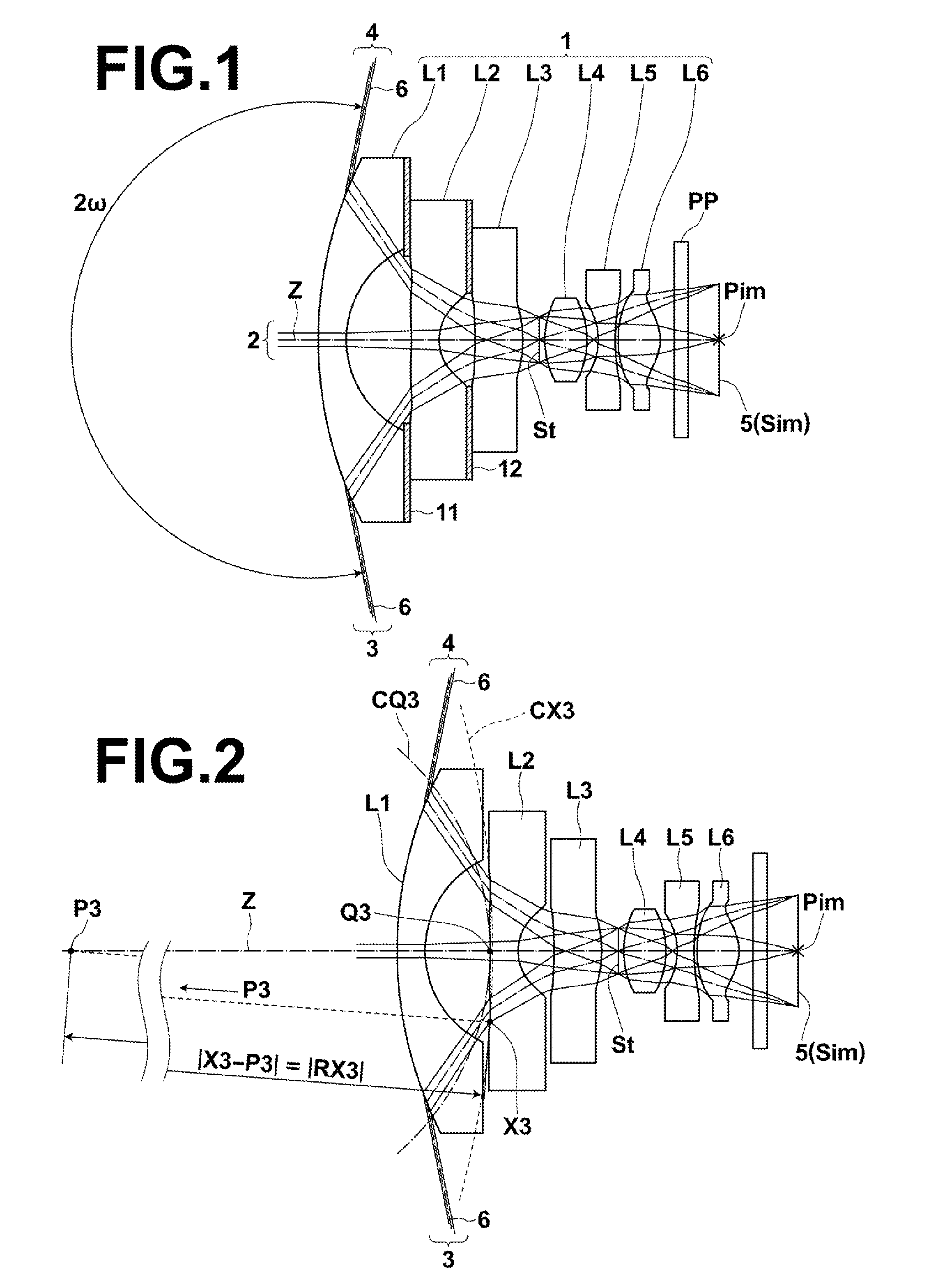
[0086]Further, in the imaging lens the object-side surface of third lens L3 has a shape having negative refractive power at a center and stronger negative refractive power at an effective diameter edge, compared with the center. When the object-side surface of third lens L3 has the shape having negative refractive power at the center and stronger negative refractive power at the effective diameter edge, compared with the center, it is possible to easily widen the angle of view, and to easily separate axial rays and off-axial rays from each other at first lens L1 and second lens L2. Therefore, it is possible to easily correct curvature of field and distortion. The shape of the object-side surface of third lens L3 will be described later in detail.

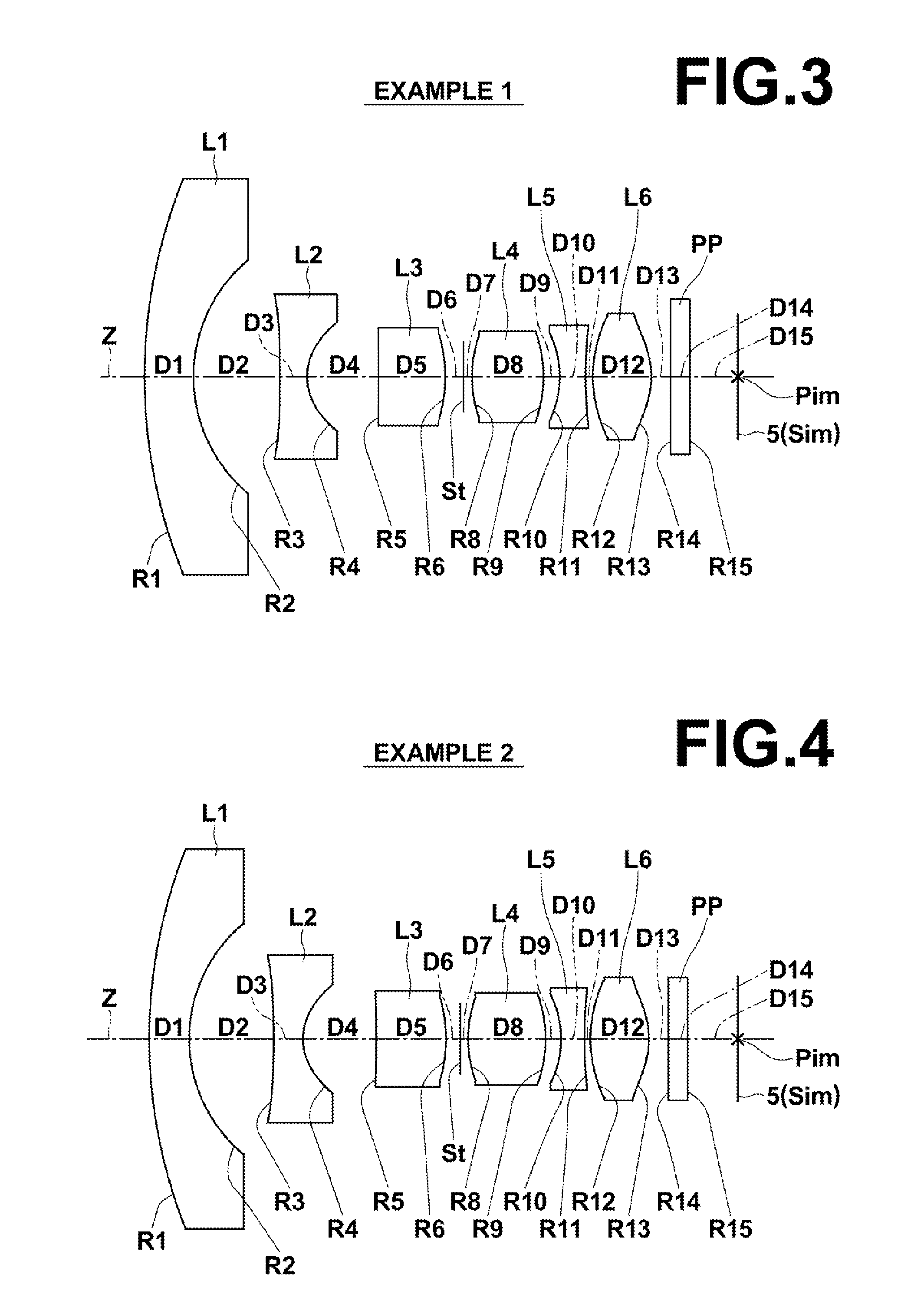
[0087]Next, the structure of a third embodiment of the present invention will be described. An imaging lens according to the third embodiment of the present invention includes negative first lens L1, negative second lens L2, positive third ...

third embodiment

[0090]Further, in the imaging lens the image-side surface of second lens L2 has a shape having negative refractive power at a center and weaker negative refractive power at an effective diameter edge, compared with the center. Further, the image-side surface of third lens L3 has a shape having positive refractive power at a center and weaker positive refractive power at an effective diameter edge, compared with the center. When the image-side surface of second lens L2 has a shape having negative refractive power at a center and weaker negative refractive power at an effective diameter edge, compared with the center, it is possible to easily correct distortion. When the image-side surface of third lens L3 has a shape having positive refractive power at a center and weaker positive refractive power at an effective diameter edge, compared with the center, it is possible to improve image qualities in a peripheral portion of an image by excellently correcting a coma aberration caused by...


PUM


Abstract

An imaging lens substantially consists of six lenses of a negative first lens, a negative second lens, a positive third lens, a positive fourth lens, a negative fifth lens and a positive sixth lens in this order from an object side. An object-side surface of the second lens is concave, and an object-side surface of the third lens is concave. A predetermined conditional formula about a combined focal length of the fourth lens and the fifth lens is satisfied.

Description

CROSS REFERENCE TO RELATED APPLICATIONS[0001]This application is a continuation of PCT / JP2012 / 005784 filed on Sep. 12, 2012, which claims foreign priority to Japanese Application No. 2011-213851 filed on Sep. 29, 2011. The entire contents of each of the above applications are hereby incorporated by reference.BACKGROUND OF THE INVENTION[0002]1. Field of the Invention[0003]The present invention relates to an imaging lens and an imaging apparatus. In particular, the present invention relates to an imaging lens appropriate for use in an in-vehicle camera, a camera for a mobile terminal, a surveillance camera, or the like using an imaging device, such as a CCD (Charge Coupled Device) and a CMOS (Complementary Metal Oxide Semiconductor). Further, the present invention relates to an imaging apparatus including the imaging lens.[0004]2. Description of the Related Art[0005]In recent years, the size of an imaging device, such as a CCD and a CMOS, became very small, and the resolution of the i...

Claims


Application Information

Patent Timeline
IPC IPC(8): G02B13/00
CPCG02B13/0015G02B13/06G02B13/0045
Inventor ASAMI, TAROKATSUMA, TOSHIAKIITO, TORUKONDO, MASATOOTOMO, RYOKO
Owner JIANGXI OFILM OPTICAL CO LTD
Why Eureka
Try Eureka