Impeller position compensation using field oriented control

a field-oriented control and position compensation technology, applied in the direction of positive displacement liquid engine, piston pump, electric commutator, etc., can solve the problems of occupying a significant amount of space between position sensors and adjustable magnetic sources, hemolysis of blood, cell damage,

Active Publication Date: 2014-07-24
TC1 LLC
View PDF7 Cites 41 Cited by
  • Summary
  • Abstract
  • Description
  • Claims
  • Application Information

AI Technical Summary

Problems solved by technology

A high shear stress can cause hemolysis of the blood (i.e., damage to cells).
However, position sensors and

Method used


Image

  • Impeller position compensation using field oriented control
  • Impeller position compensation using field oriented control
  • Impeller position compensation using field oriented control

Examples


Embodiment Construction

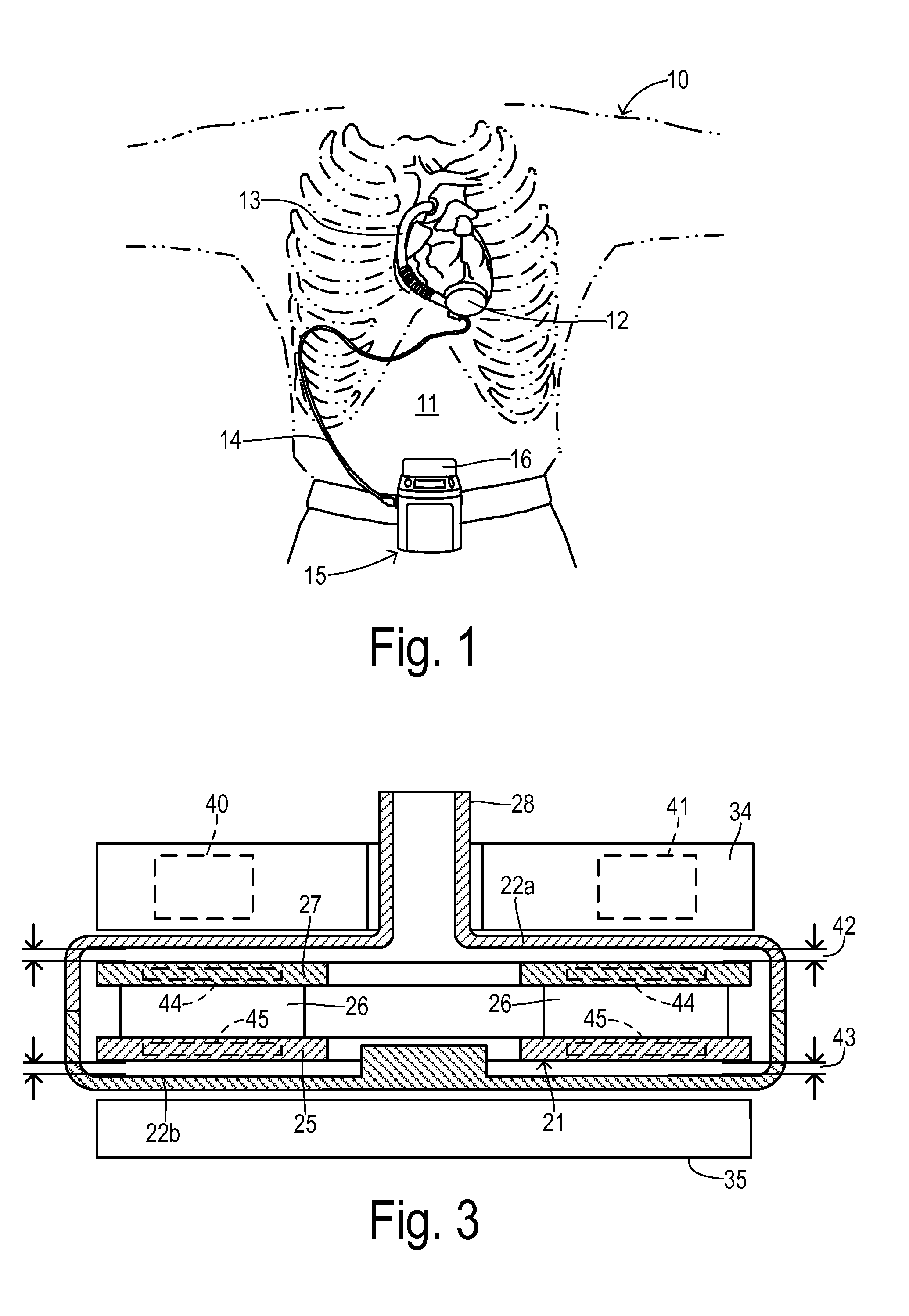
[0016]Referring to FIG. 1, a patient 10 is shown in fragmentary front elevational view. Surgically implanted either into the patient's abdominal cavity or pericardium 11 is the pumping unit 12 of a ventricular assist device. An inflow conduit (on the hidden side of unit 12) pierces the heart to convey blood from the patient's left ventricle into pumping unit 12. An outflow conduit 13 conveys blood from pumping unit 12 to the patient's aorta. A percutaneous power cable 14 extends from pumping unit 12 outwardly of the patient's body via an incision to a compact control unit 15 worn by patient 10. Control unit 15 is powered by a main battery pack 16 and / or an external AC power supply and an internal backup battery. Control unit 15 includes a commutator circuit for driving a motor within pumping unit 12.

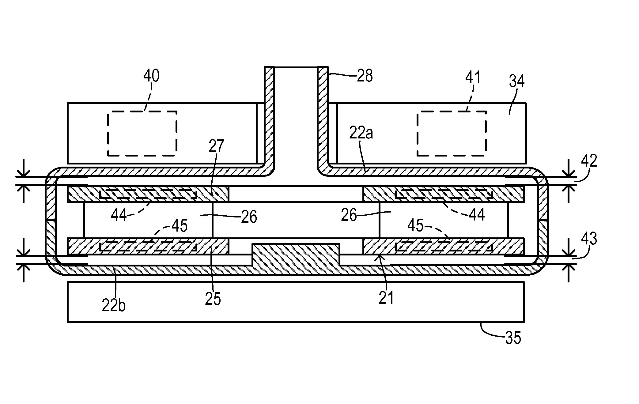
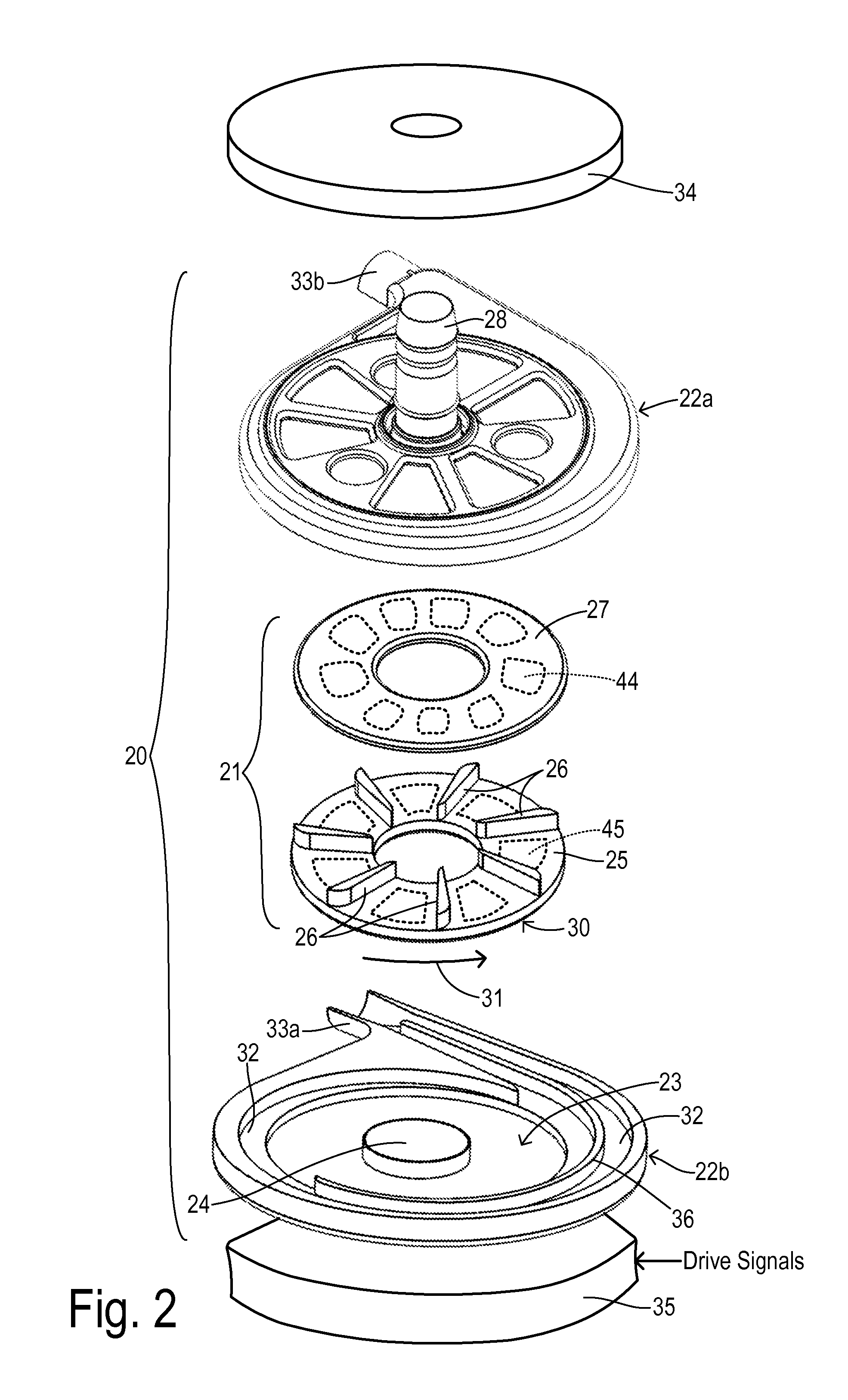
[0017]FIG. 2 shows a centrifugal pump unit 20 having an impeller 21 and a pump housing having upper and lower halves 22a and 22b. Impeller 21 is disposed within a pumping chamber 23 over...


PUM


Abstract

A centrifugal pump system having an impeller rotating with first and second magnetic structures on opposite surfaces. A levitation magnetic structure is disposed at a first end of a pump housing having a levitating magnetic field for axially attracting the first magnetic structure. A multiphase magnetic stator at a second end of the pump housing generates a rotating magnetic field for axially and rotationally attracting the second magnetic structure. A commutator circuit provides a plurality of phase voltages to the stator. A sensing circuit determines respective phase currents. A controller calculates successive commanded values for the phase voltages in response to the determined phase currents and a variable commutation angle. The angle is selected to correspond to an axial attractive force of the stator that maintains a levitation of the impeller at a centered position within the pumping chamber.

Description

CROSS REFERENCE TO RELATED APPLICATIONS[0001]Not Applicable.STATEMENT REGARDING FEDERALLY SPONSORED RESEARCH[0002]Not Applicable.BACKGROUND OF THE INVENTION[0003]The present invention relates in general to centrifugal pumping devices for circulatory assist and other uses, and, more specifically, to an improved method and apparatus for maintaining a centered position of a magnetically-levitated impeller.[0004]Many types of circulatory assist devices are available for either short term or long term support for patients having cardiovascular disease. For example, a heart pump system known as a left ventricular assist device (LVAD) can provide long term patient support with an implantable pump associated with an externally-worn pump control unit and batteries. The LVAD improves circulation throughout the body by assisting the left side of the heart in pumping blood. One such system is the DuraHeart® LVAS system made by Terumo Heart, Inc., of Ann Arbor, Mich. The DuraHeart® system employ...

Claims


Application Information

Patent Timeline
IPC IPC(8): F04B35/04
CPCF04B35/04F04D15/0088F04D29/0473F04D29/048F04D29/428F04D13/0666F04D29/041A61M60/824A61M60/422A61M60/148A61M60/232A61M60/538H02P6/18A61M60/419F04D13/024A61M2205/3303A61M2205/3507F04D7/04F04D15/0094F04D29/22F04D29/426
Inventor YANAI, MASAMICHICAMPAU, JEFFREY H.NANNA, JASON C.
Owner TC1 LLC
Why Eureka
Try Eureka