Treatment device using nanotechnology

Active Publication Date: 2014-07-24
TRANSQTRONICS LLC
24 Cites 7 Cited by

AI-Extracted Technical Summary

Problems solved by technology

Many kinds of diseases and accidents may cause harm to the human body and results in pain, wound, infection, and injury that require both swift and continuous treatments.
For example, the heat applicators nowadays are generally bulky and difficult to fit onto small wounds or injuries at locations that are hard to access.
In addition, the regular heating applicators are not long lasting, requiring frequent change of the applicator.
Thirdly, some of the heat applicators are hard to ...

Benefits of technology

[0028]It is yet another object of the current invention to provid...

Abstract

The current invention discloses a treatment device having a heat source, a power source and a heat applicator. The power source includes at least one nanotech battery, ensuring superior properties such as prolonged electricity production and prompt recharging. The heat applicator includes a heat conductive layer made from nanofibers, providing highly efficient heat distribution to the targeted regions. The power source provides energy to the heat source, which generates heat so that the applicator may distribute to an injury site or wound bed of a user. The current device may also be used for cooling, instead of heating applications. In addition to the medical utilizations, the current device may also play a central role in other apparatus that require thermal control capabilities.

Application Domain

Therapeutic coolingTherapeutic heating

Technology Topic

Heat distributionElectrical battery +8

Image

  • Treatment device using nanotechnology
  • Treatment device using nanotechnology

Examples

  • Experimental program(1)

Example

[0032]The preferred embodiments of the present invention will now be described with reference to the drawings. Identical elements in the various figures are identified, as far as possible, with the same reference numerals. Reference will now be made in detail to embodiments of the present invention. Such embodiments are provided by way of explanation of the present invention, which is not intended to be limited thereto. In fact, those of ordinary skill in the art may appreciate upon reading the present specification and viewing the present drawings that various modifications and variations can be made thereto without deviating from the innovative concepts of the invention.
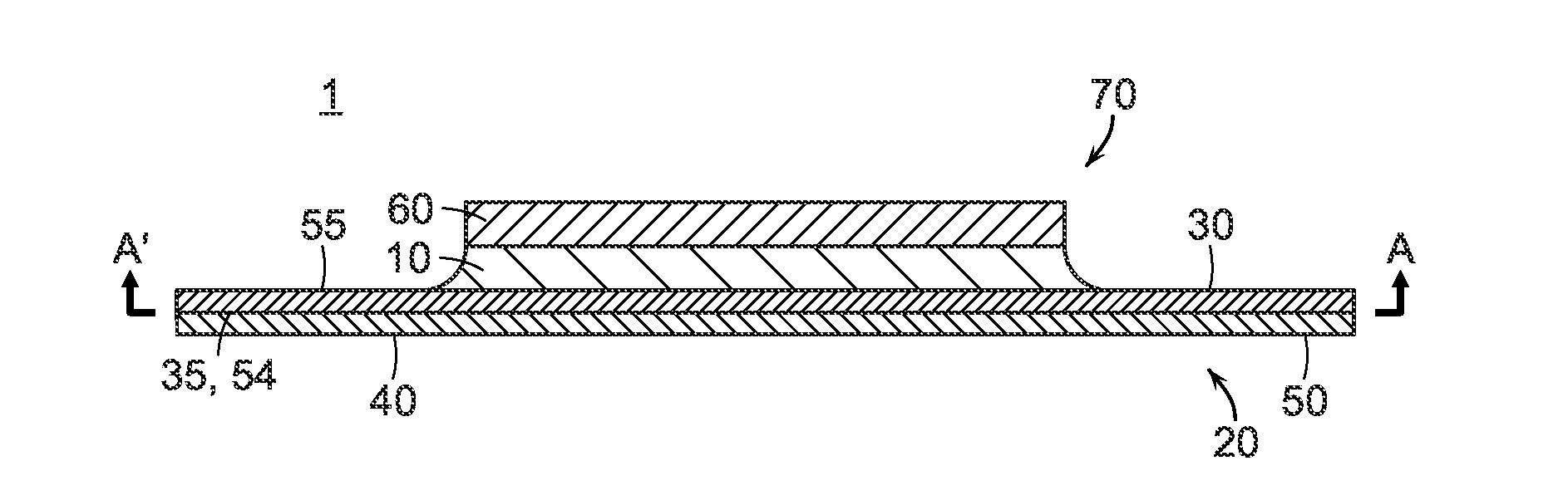
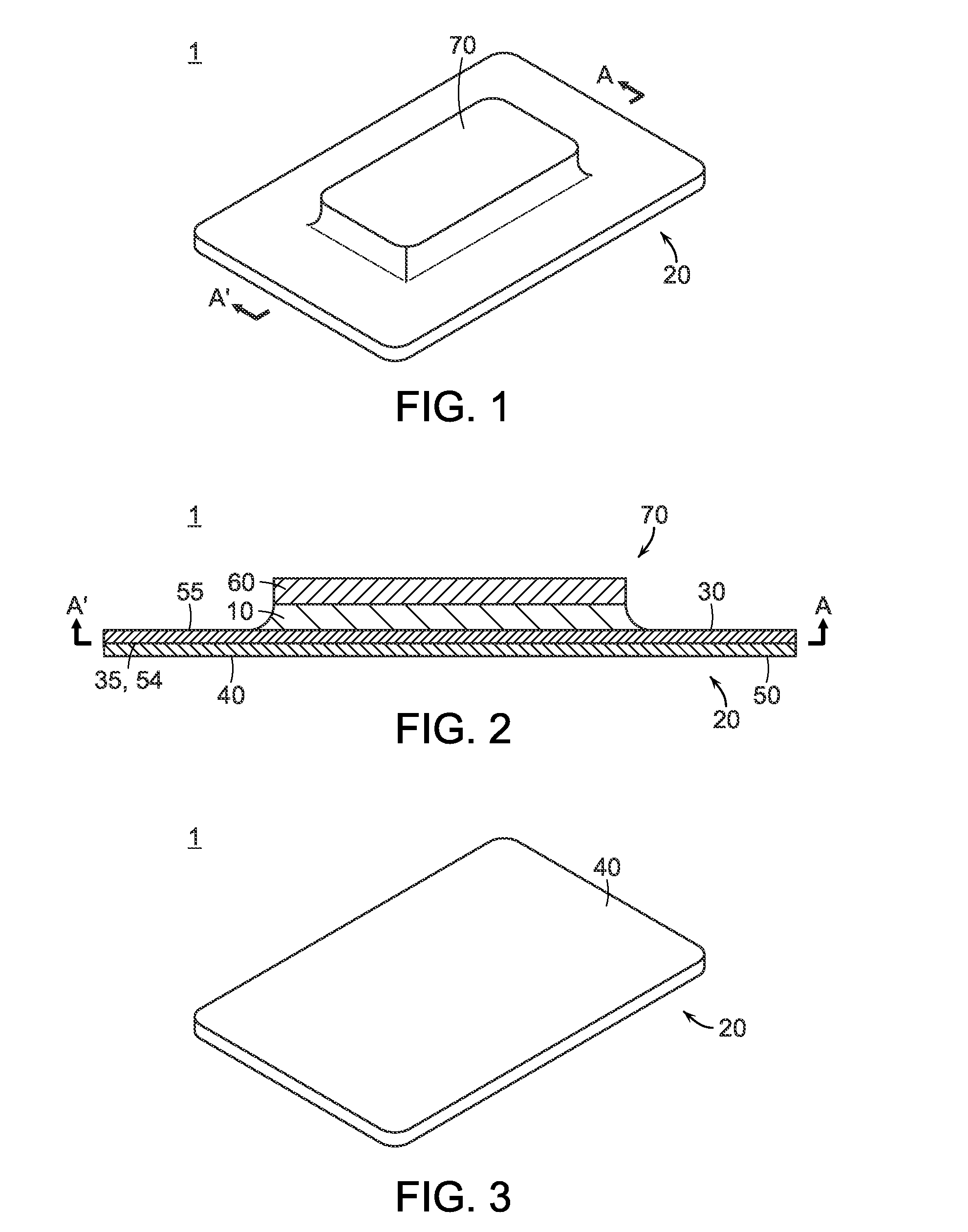
[0033]FIG. 1 shows a back perspective view of a treatment device embodying the current invention. Shown in FIG. 1 is the treatment device 1 having a heat generating body 70 attached to a heat applicator 20.
[0034]FIG. 2 shows a sectional view of the treatment device shown in FIG. 1, as indicated by markers A and A′. Shown in FIG. 2 is the treatment device 1 having a heat generating body 70 attached to a heat applicator 20. The heat generating body 70 comprises a heat source 10 and a power source 60, wherein the heat source 10 and power source 60 are preferably connected by wires (not shown). In addition, the heat applicator 20 comprises a heat application layer 30 and a heat conductive layer 50, wherein the heat application layer 30 has a heat receiving surface 35 and a heat application surface 40, and the heat conductive layer 50 has a front side 54 and a back side 55. The front side 54 of the heat conductive layer 50 directly engages with the heat receiving surface 35 of the heat application layer 30. The heat application surface 40 is designed to engage exposed human wound beds or injury sites.
[0035]FIG. 3 shows a front perspective view of the treatment device 1. Shown in FIG. 3 is the heat application surface 40 of the heat application layer 30, which is part of the heat applicator 20.
[0036]FIGS. 1, 2 and 3 show an embodiment of the current invention. However, it should be noted that the design of the current invention may vary significantly from the embodiment herein described. As long as the general inventive spirit stays consistent with the disclosure, the variations of embodiments should be considered part of the current invention. While some of the variations are hereby described, the other variations may be considered general knowledge to a person skilled in the art so that they do not required detailed discussion. The teachings and disclosures of the current invention encompass all the variations.
[0037]The power source 60 of the current invention may employ any kind of electricity generating or storing devices. Preferably, the power source here is a rechargeable battery using nanotechnology. For example, the nanotech battery may use silicon nanowires on stainless steel substrate, providing 10 times the power density of conventional lithium ion batteries. Alternatively, the nanotech battery may use aligned carbon nanotubes on a substrate to establish the anode or cathode in a conventional battery, improving the power generating capacity by almost 10 fold. More preferably, the power source is a battery utilizing nanotech supercapacitor technology, which can be recharged promptly. For instance, by using grapheme on the surface of anodes to make lithium-ion batteries, the batteries may be recharged 10 times faster than common rechargeable batteries. The fast recharging nanotech batteries are particularly suitable as the power source 60 herein included in the current invention. With such designs, the treatment device may be used more widely in emergency situations because the initiation of treatment and alternation of devices may become more time-saving and efficient.
[0038]In addition to the technologies described above, the power source 60 may also use other nanotechnology, such as but not limited to: lithium sulfur batteries (using carbon nanofibers encapsulating the sulfur in the cathode or using mesoporous carbon nanoparticles that embraces sulfur inside the nanopores of the cathodes), nanocomposite batteries (using cathodes made of a nanocomposite designed to increase the energy density of the Li-ion batteries), nano-structured lithium titanate battery having enhancing charge/discharge capability, fast charge/recharge batteries using silicon nanoparticles coating a titanium disilicide lattice, thermocells using nanotubes that generate electricity, electrical generator built with nanostructured material that can generate electrical power from the user's body motion such as walking, and ultracapacitor batteries using single atom thick grapheme sheets, and any combinations of batteries and power sources thereof.
[0039]Besides incorporating nanotechnology batteries, the power source 60 may also utilize other readily available supplies of electricity. For example, the power source 60 may be a power cord and power plug that can be directly connected to a common alternating current electricity outlet. Alternatively, the power source 60 may be a regular battery or battery pack, either rechargeable or non-rechargeable. The battery may be a regular AAA zinc-carbon or alkaline battery, or any other type or size that may fit the energy needs and/or physical accommodations of the current treatment device.
[0040]The heat source 10 is used to produce heat from the electricity generated by the power source 60. The design of the heat source 10 is generally known in the art and it may vary according to the characteristics of the electricity produced by the power source 60 and the specific requirements of the user and the injury/wound/infection to be treated. The heat source 10 may be a separate structure from the power source 60, or on the alternative, a part of an integrated structure, such as a heat generating body 70, which also includes the power source 60. The connection between the heat source 10 and the power source 60 may vary as well. In an alternative embodiment, the heat source 10 is removably attached to the power source 60, wherein after the heat source is considered to have produced enough heat, the power source 60 is detached from the heat source 10 and the rest of the treatment device 1, which is used to treat the wound bed or injury site, reducing the weight the treatment device and allowing the user of the treatment device to move around more freely. In another embodiment, the power source 60 may be connected to a plurality of heat sources 20 by long wires to ensure continued power supply to a number of treatment devices.
[0041]The heat applicator 20 is designed to apply the heat produced by the heat source 10 to the user of the treatment device. The heat applicator 20 in the current embodiment has a heat application layer 30 and a heat conductive layer 50. However, it should be noted that the heat application layer 30 and the heat conductive layer 50 may be a single layer integrated together and having both heat application and heat conducting capabilities. As to the embodiment shown in FIG. 2, the heat conductive layer may be made from woven or unwoven nanofibers that are extensively affixed to the back side of the heat application layer 30. The nanofibers used in the heat conductive layer 50 may include but not limited to: norganic nanofibers such as ceramic nanofibers made from titanium dioxide (TiO2), silicon dioxide (SiO2), zirconium dioxide (ZrO2), aluminum oxide (Al2O3), lithium titanate (Li4Ti5O12), and titanium nitride (TiN) or platinum (Pt), organic or polymer nanofibers such as but not limited to polystyrene, polyacrylonitrile, polycarbonate, PEO, PET and water-soluble polymer nanofibers, and bi-component nanofibers, and any combinations thereof. The key property of the nanofibers making up the heat conductive layer 50 is that the nanofibers are capable of efficient transferring and distribution of heat. For example, the thermally treated carbon nanofibers produced by Aldrich (Pro. No. 719781) may be used for the heat conductive layer. In addition, the nanofibers of the heat conductive layer 50 may be capable of prolonged and controlled distribution of heat.
[0042]The heat application layer 30 is preferably made from thin and absorbent material so that it may evenly distribute the heat generated by the heat source to the wound bed or injury site and it may absorb the exudates, if any is produced by the wound or injury. As indicated above, the heat application layer 30 may be integrated with the heat conductive layer 50, forming a single layer. Thus, the materials usable for the heat conductive layer 50, as indicated above, may also be utilized for the heat application layer 30. In addition, the heat application layer 30 may be made from materials such as but not limited to: woven or unwoven fabric, cloth, terrycloth, woven or woven fibers of wool, flax, cotton, and/or yarn, mineral textiles such as but not limited to asbestos, glass and/or fiberglass, and synthetic textile including but not limited to nylon, polyester, and/oracrylic, or any combinations thereof. The heat application layer 30 may have a heat application surface 40, which may be sticky or have a sticky edge to ensure covering or partial covering of the wound, infection or injury. The treatment device 1, in its unused form, may further include a non-sticky layer attached to the heat application surface 40. The non-sticky layer may be removed before use, allowing the treatment device to be securely attached.
[0043]In the current embodiment as shown in FIGS. 1, 2 and 3, the heat applicator 20 and heat generating body 70 are both shown as having a rectangular shape. It should be noted that the shape and size of the heat applicator 20 and the heat generating body 70, as well as various components of the treatment device 1, may vary according to the specific design of the device, the need of the user and the wound/infection/injury to be treated. The device and its components may take any shape also due to the extensive use of the current invention. For instance, the device may integrated into a mask, used for the treatment of acne with the capacity to activate specific regions conforming the area(s) of concern. As indicated below, the device herein disclosed may also utilize in applications that generally require thermal control. For example, the device may be made into pads, strips, or even clothing, in order to satisfy the specific need of the application. The size of the applicator may range from 1 mm2 to 10 m2, with the preferred range of 10 mm2 to 100 cm2. The weight of the treatment device 1 is preferable light, ranging from 0.1 g to 10 kg, and a preferred range of 1 g to 1 kg. The components of the device are preferably removably attached so that each part may be detached from the others and used separately. The applicator portion of the device may be cut or divided into intended size and shape to ensure convenient application.
[0044]Instead of a heat source 10, as indicated above, the treatment device 1 may include a refrigerating unit to make the treatment device capable of reducing temperature. Such an alternation allows the treatment device to be used similar as a cold pack, which may stabilize some injuries/wounds and facilitate recovery.
[0045]The current treatment device may be used for any kind of wounds, infections, injuries, and ailments. In addition, the current device may also be used to prevent wound infection by heating a target area prior to surgery. The basic function of the treatment device is to alter the temperature of an external injury site or wound bed to enhance healing and facilitate recovery. In addition, the current treatment device may be used for pain management, mainly by promoting blood flow and improving recovery. The current device may also be used to apply heat treatment for acne and other skin disorders, mainly by inhibiting the growth and development of bacteria affecting the illness. In organ transplantation, this device may be used to control and maintain the temperature of the transplant organs during transportation and storage of the transplant organs, as the organs require specific temperature control.
[0046]Beside its medical applications, the current device may also be used as other heating or cooling apparatus, such as but not limited to clothing apparel and accessories including gloves/hand warmers, jackets, pants, socks, shoe insert, ear muffs, footwear such as ski boots, and winter boots, ski equipment, goggles, ice skates, seat pads, portable seat cushions, and heatable or coolable containers. In particular, the device may be incorporated into mattress, bed cushions, mattress covers, comforters, pillows, and bed linens, etc, for the treatment of bed bugs, as bed bugs are sensitive to increased temperature. A thermal cover could also be used to encase an entire mattress and or bed. Alternatively, the current nanotech heating device may be included in a thermal bag, which may be used in the management of bed bugs by treating bed linens, comforters, pillows, as well as clothes. In addition, the fast-charging and long-lasting nature of the current device allows the device to be included a thermal blanket. The thermal blanket may be used for the treatment of hypothermia and the treatment of cardiac arrest with medically induced hypothermia. As long as the apparatus requires thermal control capability, the current invention may play a central role.
[0047]As indicated above, the treatment device may further comprise a control mechanism connected to the power source. The control mechanism may be used to initiate, terminate, and adjust the electricity provided by the power source, thus controlling thermal alternation capability of the device. With the control mechanism, the user of the treatment device may easily control the treatment process and change the durations, cycles, and intensity of the treatments.
[0048]Although this invention has been described with a certain degree of particularity, it is to be understood that the present disclosure has been made only by way of illustration and that numerous changes in the details of construction and arrangement of parts may be resorted to without departing from the spirit and the scope of the invention.

PUM

no PUM

Description & Claims & Application Information

We can also present the details of the Description, Claims and Application information to help users get a comprehensive understanding of the technical details of the patent, such as background art, summary of invention, brief description of drawings, description of embodiments, and other original content. On the other hand, users can also determine the specific scope of protection of the technology through the list of claims; as well as understand the changes in the life cycle of the technology with the presentation of the patent timeline. Login to view more.

Similar technology patents

Disposable medical-examination light

ActiveUS20090097236A1good visualizationeasy to use
Owner:UTAH MEDICAL PRODS

Patient positioning support structure

ActiveUS20120198625A1easy to useinexpensive to make
Owner:WARSAW ORTHOPEDIC INC

Classification and recommendation of technical efficacy words

  • easily manufacture
  • easy to use

Dispensing system

ActiveUS20070278164A1easily manufactureprevent theft
Owner:WESTROCK SHARED SERVICES LLC

Reciprocating compressor and manufacturing method thereof

InactiveUS20060024181A1easily manufactureprevent abrasion
Owner:LG ELECTRONICS INC

Laser assisted total joint arthroplasty

InactiveUS20090234360A1easy to use
Owner:ALEXANDER VLADIMIR

Enclosure for a portable hemodialysis system

ActiveUS20090114582A1easy to use
Owner:DEKA PROD LLP
Why Eureka
Try Eureka