Braking force control apparatus for vehicle

a technology for controlling apparatus and braking force, which is applied in the direction of braking components, process and machine control, electric devices, etc. it can solve the problems of time lag in terms of control, inability to provide appropriate control properties, and usually set backlash in power transmission systems, etc., to prevent backlash, improve control efficiency, and improve control efficiency

Active Publication Date: 2014-07-24
TOYOTA JIDOSHA KK
View PDF6 Cites 15 Cited by
  • Summary
  • Abstract
  • Description
  • Claims
  • Application Information

AI Technical Summary

Benefits of technology

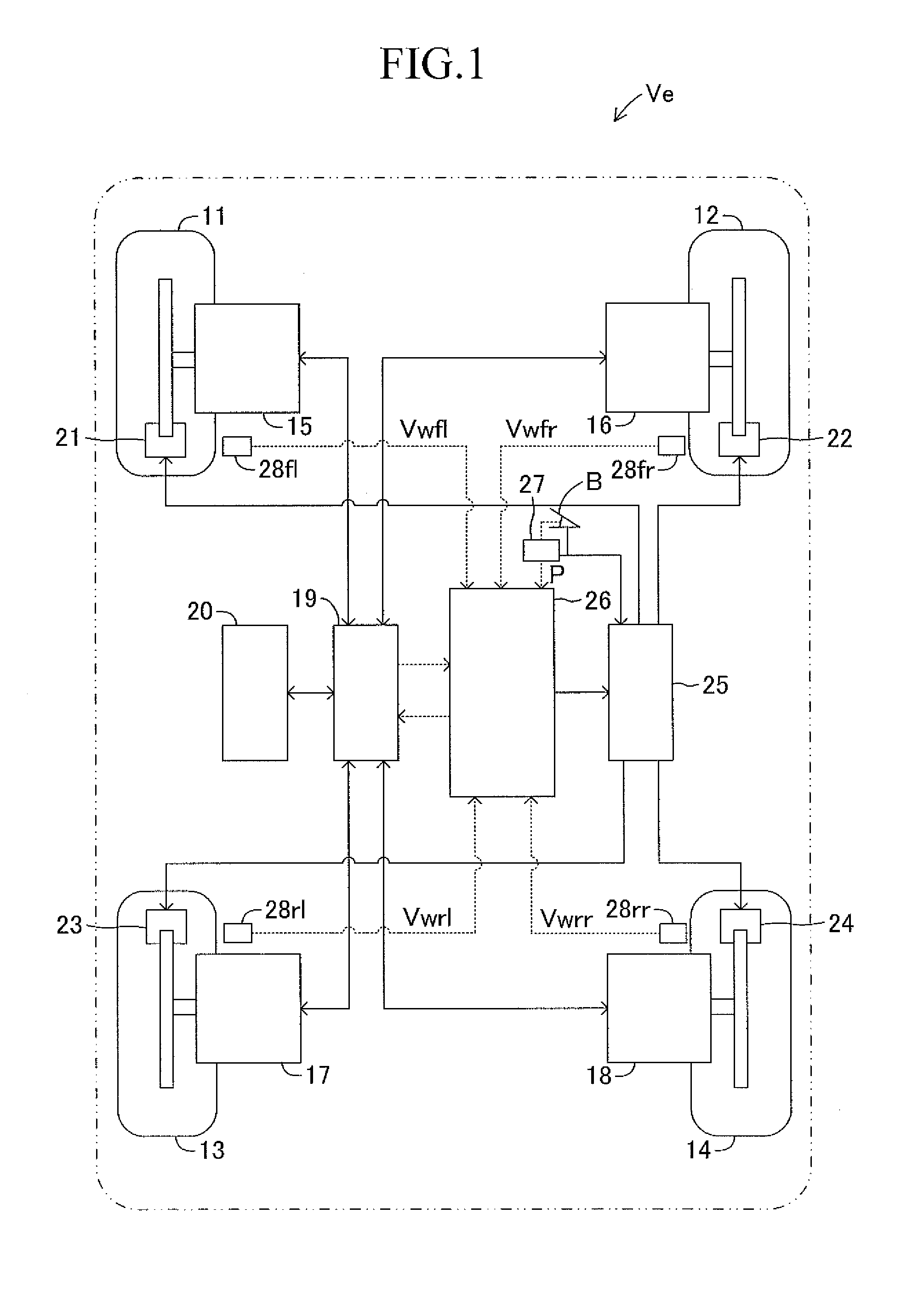
[0033]As a result, the tendency of the lock of the wheel can be avoided, thereby appropriately braking the vehicle. Then, also in this case, when the state is caused to transition, the inverting state where the electromagnetic driving force and the electromagnetic braking force are repeatedly generated does not occur, and the mechanical braking force by the braking force generation mechanism activated in cooperation with the electromotive force generation mechanism does not fluctuate. Thus, the driver does not feel the sense of discomfort caused by the fluctuation in the braking force generated on the wheels to surely avoid the tendency of the lock of the wheel, and to appropriately brake the vehicle. Moreover, also in this case, the acting direction of the electromagnetic driving force or the electromagnetic braking force generated by the electromotive force generation mechanism can be maintained in one direction, and thus, for example, the time lag in terms of control generated by reducing the backlash in the power transmission system to the wheel of the electromotive force generation mechanism is not generated, and the noise caused by the backlash can be prevented from being generated. Thus, extremely excellent responsiveness is secured, thereby quickly converging the state transition, and generating appropriate braking forces on the wheels.
[0034]In this case, the braking control means can, in the case where the state is caused to transition, use, when a magnitude of a friction coefficient of a road surface on which the vehicle travels is smaller than a magnitude of a predetermined friction coefficient, the electromagnetic driving force or the electromagnetic braking force generated by the electromotive force generation mechanism so as to avoid the tendency of the lock of the wheel; and use, when the magnitude of the friction coefficient of the road surface on which the vehicle travels is equal to or more than the magnitude of the predetermined friction coefficient, the mechanical braking force generated by the braking force generation mechanism so as to avoid the tendency of the lock of the wheel.

Problems solved by technology

In this case, a backlash is usually set in a power transmission system (such as a speed reduction machine) provided between the motor and the wheels.
Therefore, for example, when the torque to be generated is inverted by the regeneration control and the power running control for the motor for driving, a time lag in terms of control may occur, and an appropriate control property may not be provided.
Moreover, when the motor for driving is activated by means of the regeneration control and the power running control, the set backlash is reduced, resulting in tendency of noise generation, which makes a driver feel sense of discomfort.

Method used


Image

  • Braking force control apparatus for vehicle
  • Braking force control apparatus for vehicle
  • Braking force control apparatus for vehicle

Examples


second embodiment

b. Second Embodiment

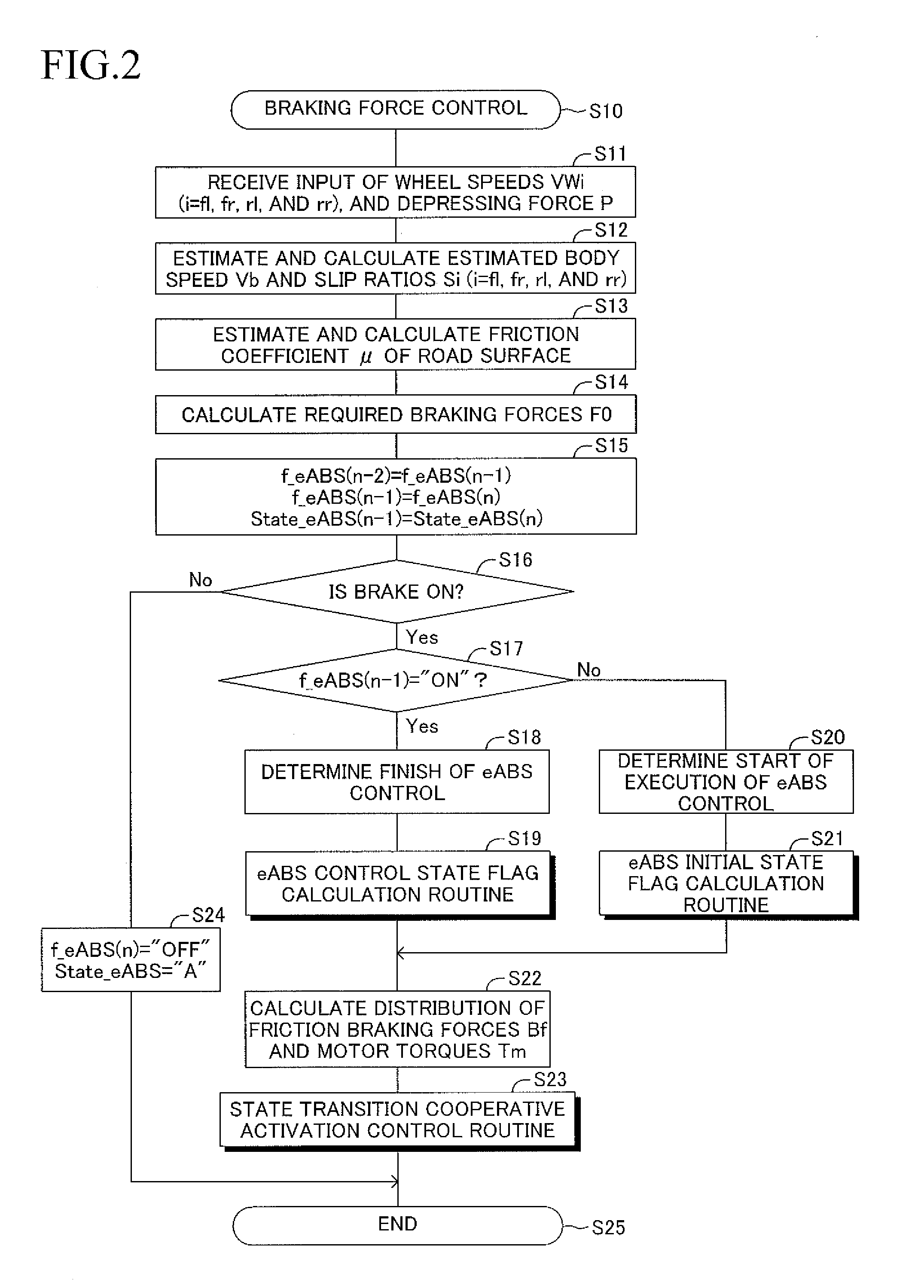
[0190]The first embodiment is realized in a manner that the magnitudes of the required braking forces F0 (ideal braking forces μW) are determined by executing the braking control program, and the magnitudes (distribution) of the friction braking forces Bf and the magnitudes (distribution) of the motor braking torques Tmr or the motor driving torques Tmc are determined depending on the eABS control state (state A or state B) in order to impart the determined required braking forces F0 (ideal braking forces μW) to the vehicle Ve. In this case, appropriate determination of the magnitudes of the required braking forces F0 (ideal braking forces μW) may become difficult depending on the traveling state (traveling environment) of the vehicle Ve and the like. Thus, according to a second embodiment of the present invention, the electronic control unit 26 executes the state transition cooperative activation control routine illustrated in FIG. 16, thereby appropriately carr...

third embodiment

c. Third Embodiment

[0203]The first embodiment, the variation thereof, and the second embodiment are realized in a manner that the electronic control unit 26 executes the eABS control state flag calculation routine to cause the eABS control state to transition from the state A to the state B, for example, when the friction coefficient μ of the road surface decreases below the predetermined road surface friction coefficient μ0 on an extremely-low-μ road. In other words, the first and second embodiments are realized in a manner that the eABS control state is caused to transition depending on an environment (more specifically, the road surface state and the like) in which the vehicle Ve is traveling.

[0204]By the way, as described in the first embodiment, the variation thereof, and the second embodiment, the driver is effectively prevented from feeling the sense of discomfort and sensing the noise caused by the transition of the eABS control state by maintaining, in one direction, the ch...


PUM


Abstract

An electronic control unit of a braking force control apparatus for a vehicle activates, as a first state, in-wheel motors in a regeneration state, thereby generating motor braking torques, and causes friction brake mechanisms to generate friction braking forces. Moreover, the unit activates, as a second state, the motors in a power running state, thereby generating motor driving torques, and causes the mechanisms to generate friction braking forces. Then, when the state is caused to transition between the first state and the second state, the unit changes magnitudes of the braking torques or the driving torques generated by the motors to one of increase and decrease, and changes magnitudes of the friction braking forces generated by the mechanisms to one of increase and decrease.

Description

TECHNICAL FIELD[0001]The present invention relates to a braking force control apparatus for a vehicle, which is configured to control braking forces of a vehicle, and more particularly, to a braking force control apparatus for a vehicle, which is configured to appropriately avoid a lock state of wheels during braking.[0002]Conventionally, for example, a braking control apparatus for an electric vehicle disclosed in Patent Literature 1 has been known. The related-art braking control apparatus for an electric vehicle maintains, while ABS control is being carried out, a hydraulic braking force command value to the same value as a previous hydraulic braking force command value, that is, maintains a mechanical braking force constant, and simultaneously controls a torque of a motor for driving in a range from a regeneration mode to a power running mode.[0003]Moreover, conventionally, for example, a braking force control apparatus disclosed in Patent Literature 2 has also been known. Durin...

Claims


Application Information

Patent Timeline
Patent Type & Authority Applications(United States)
IPC IPC(8): B60T8/17B60L7/18B60T11/04B60T8/176B60T8/1755
CPCB60T8/17B60T8/176B60L7/18B60T11/04B60T8/1755B60T2270/604B60T1/10B60T13/586B60L3/108B60L7/26B60L15/2009B60L2220/44B60L2260/26B60K28/16B60W10/08B60W10/184B60W30/02B60W30/18127B60W2520/26B60T8/17616Y02T10/64Y02T10/72
Inventor AKAHO, DAISUKENAKATSU, MASATOSHI
Owner TOYOTA JIDOSHA KK
Why Eureka
Try Eureka