Crankcase ventilation for an internal combustion engine, tank ventilation conduit and connection system therefor

a technology for internal combustion engines and venting conduits, which is applied in the direction of couplings, air intakes for fuel, non-fuel substance addition to fuel, etc., can solve the problems of inability to prevent the environment from being adversely affected, the maximum insertion force of the safety device of this type is reduced, and the insertion force is reduced. , to achieve the effect of facilitating visual detection of the connection state, and reducing the maximum insertion for

Active Publication Date: 2014-07-31
A KAYSER AUTOMOTIVE SYST
View PDF4 Cites 25 Cited by
  • Summary
  • Abstract
  • Description
  • Claims
  • Application Information

AI Technical Summary

Benefits of technology

[0010]In the relaxed, i.e. non-compressed or non-expanded state, the retaining ring projects out of the first or second groove such that the retaining ring can snap into or engage the second or first groove by displacing the first pipe connector in the receiving chamber and correspondingly displacing the retaining ring to the second or first groove. In this way, the retaining ring ensures the connection state due to its engagement with both grooves. In other words, in both embodiments, the retaining ring in the relaxed state overlaps both with the diameter of the first groove and the second groove such that the retaining ring snapped into both grooves prevents any relative axial displacement of the two pipe connectors.
[0021]More preferably, the insertion chamfer is arranged such that before a compression of the radial seal, the retaining ring is compressed or expanded when the first pipe connector is inserted into the receiving chamber. In this way, the insertion force is reduced, as the compression or expansion of the retaining ring occurs with a time delay with respect to the compression of the radial seal. Thus, the maximum insertion force can be reduced significantly.
[0022]Preferably, the first pipe connector further comprises a collar which is insertable into an enlarged-diameter portion of the second pipe connector and which substantially completely enters into the enlarged-diameter portion in the completely coupled state. In this way, the state of complete connection can be detected easily by an installer as the collar completely enters into the enlarged-diameter portion and does not protrude therefrom any longer or is substantially flush with this portion.
[0023]More preferably, the collar is color-coded at its circumference, for example using signal red. This enables a much easier visual detection of the connection state.
[0024]A state of incomplete connection is thus quickly identified and any operation of the motor vehicle in this state and the corresponding pollution of the environment can be prevented in a secure manner.

Problems solved by technology

However, if the ventilation conduit is not properly connected or is for example accidentally not being connected during repair or maintenance of the internal combustion engine, gases escape from the crankcase into the environment such that a pollution of the environment occurs.
However, a safety device of this type is complicated and costly.
In addition, such a safety device only provides information about the error state, but cannot prevent the internal combustion engine from being operated despite of the error and thus cannot prevent the environment from being adversely affected.

Method used


Image

  • Crankcase ventilation for an internal combustion engine, tank ventilation conduit and connection system therefor
  • Crankcase ventilation for an internal combustion engine, tank ventilation conduit and connection system therefor
  • Crankcase ventilation for an internal combustion engine, tank ventilation conduit and connection system therefor

Examples


Embodiment Construction

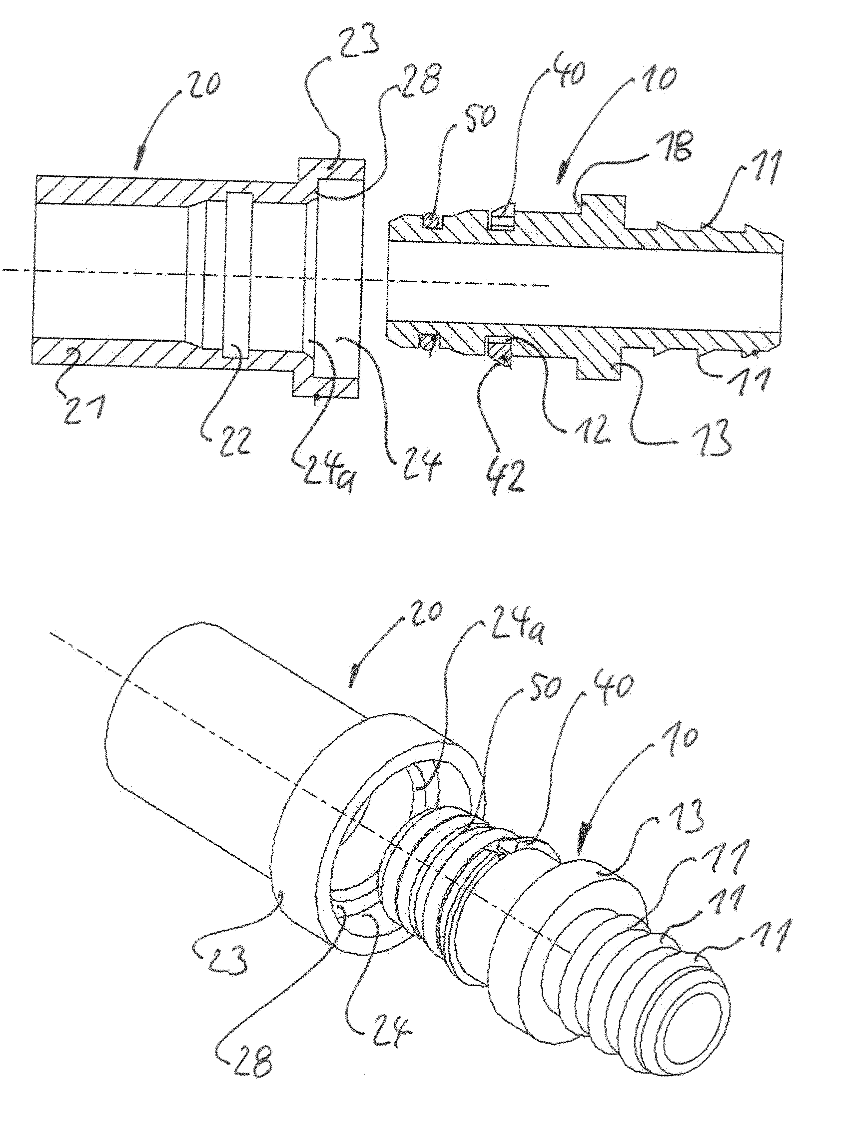
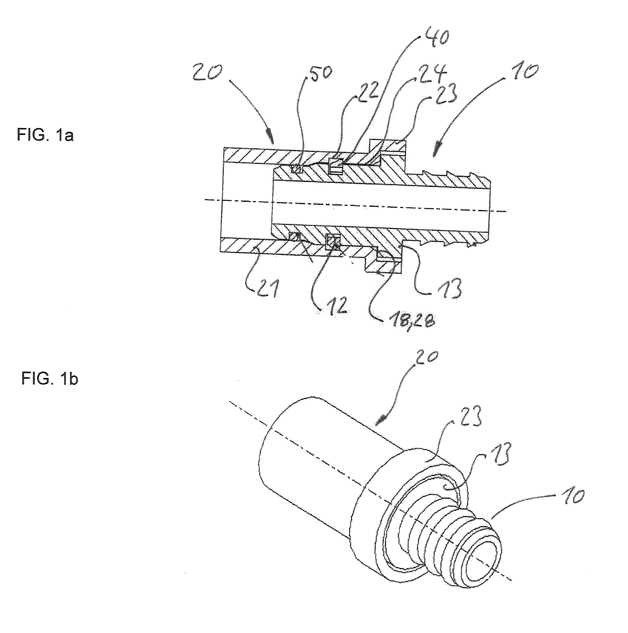
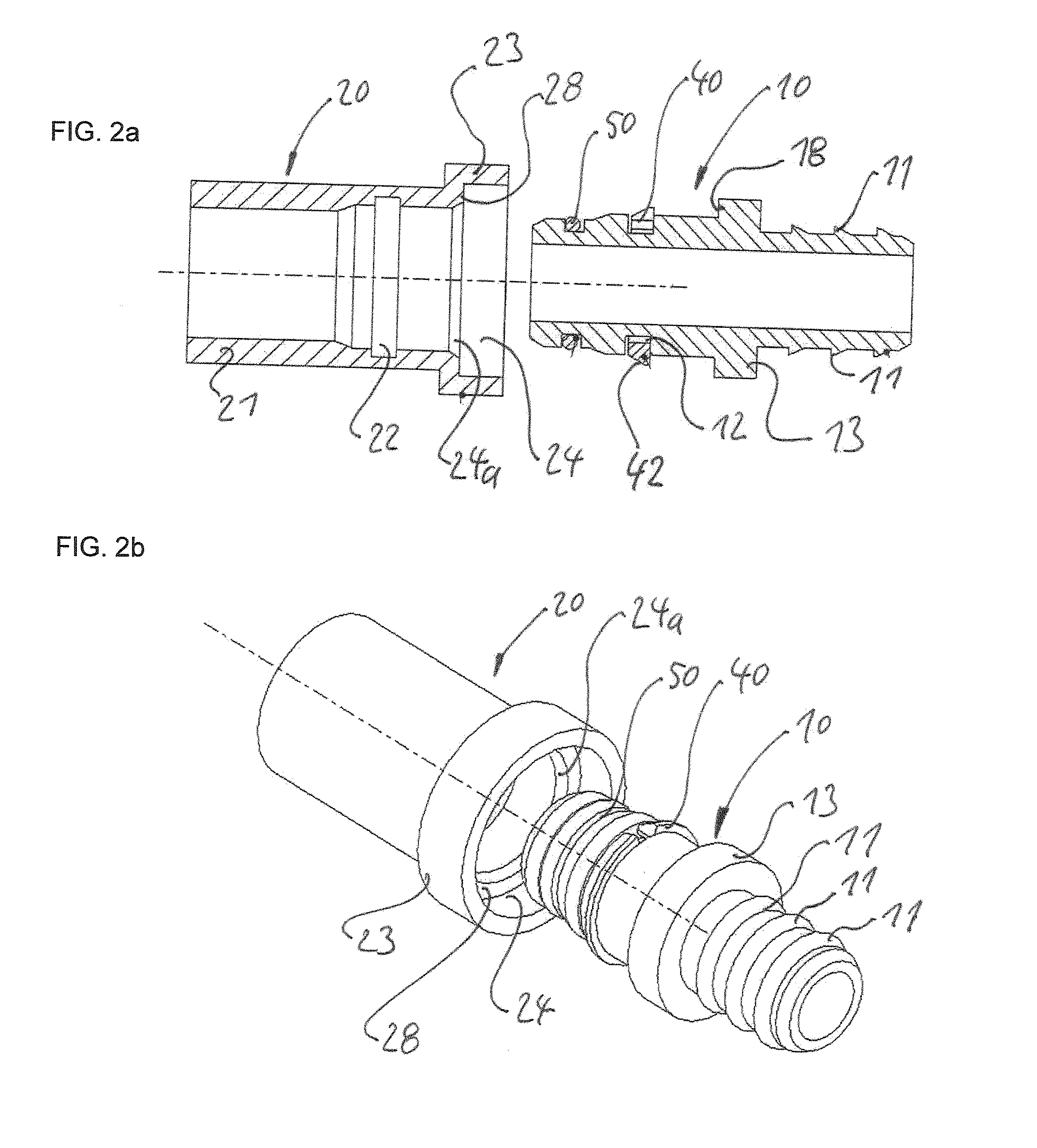
[0039]With reference to the figures, one embodiment of the invention and its variants will be described in more detail. Here, in FIGS. 3a to 12b which show variants of the embodiment, for the sake of clarity, only those elements are provided with reference numbers, which are different from the elements of the embodiment. All other elements correspond to those of the embodiment.

[0040]The additional elements in the variants of FIGS. 3a to 12b may be combined freely to form further variants.

[0041]Although in the embodiment and its variants, a first pipe connector 10 is connected to a second pipe connector 20, the term “pipe connector” should be understood as a fitting which may be a further fluid conduit or a fitting connector of a further component, such as an intake conduit of an internal combustion engine. Furthermore, the pipe connector 10, 20 does not necessarily have a straight configuration, as shown in the figures, but may have any other shape or configuration, such as a 90° be...


PUM


Abstract

A crankcase ventilation for an internal combustion engine with a ventilation conduit which connects the crankcase of the internal combustion engine to an intake duct of the internal combustion engine, as well as a tank ventilation conduit and a connection system for a fluid conduit. The ventilation conduit comprises: a first pipe connector (10), and a second pipe connector (20) with a receiving chamber (24) into which the first pipe connector (10) is insertable, wherein a second groove (22) is formed in the receiving chamber (24), and the first pipe connector (10) has a first groove (12), wherein a compressible retaining ring (40) is inserted into the first groove (12), the compressible retaining ring being engageable with the second groove (22) when the first pipe connector (10) is inserted into the receiving chamber (24), or an expandable retaining ring is inserted into the second groove (22), the expandable retaining ring being engageable with the first groove (12) when the first pipe connector (10) is inserted into the receiving chamber (24).

Description

BACKGROUND[0001]1. Field of the Invention[0002]The present invention relates to a crankcase ventilation for an internal combustion engine as well as a tank ventilation conduit for a motor vehicle and a connection system for a fluid conduit containing fuel vapor or a combustion gas in a motor vehicle and comprising a non-detachable plug connection.[0003]2. Description of the Related Art[0004]Since many years, regulations require that ventilation means of the crankcase of internal combustion engines in motor vehicles are not connected to the atmosphere, but to the intake duct of the internal combustion engine such that combustion gases entering into the crankcase and engine oil mixed with the combustion gases can be sucked in and burned by the engine. In this way, a pollution of the environment due to leaking uncleaned combustion gases and leaking engine oil can be prevented.[0005]As described for example in DE 38 24 791 A1, a ventilation conduit for a crankcase ventilation mostly com...

Claims


Application Information

Patent Timeline
Patent Type & Authority Applications(United States)
IPC IPC(8): F16L21/035
CPCF16L21/035F01M13/022F02M35/10F16L37/14F16L37/088F01M13/0416F01M13/023F01M13/04F02M25/06
Inventor KAHLE, FRANKFRETER, HEIKO
Owner A KAYSER AUTOMOTIVE SYST
Why Eureka
Try Eureka