Stator of an Alternator

Inactive Publication Date: 2014-07-31
VICTORY INDAL
View PDF10 Cites 11 Cited by
  • Summary
  • Abstract
  • Description
  • Claims
  • Application Information

AI Technical Summary

Benefits of technology

The invention is a stator for an alternator that makes wire winding more convenient and increases the density of wires in the stator grooves, reducing the thickness of the wires and improving the alternator's capacity to generate electricity. After winding, the wires are compacted to increase their tightness in the grooves. This results in a more efficient and compact electrical generator.

Problems solved by technology

However, since the stator is annular, openings of the grooves are oriented toward the center thereof, and this structure would make the winding action difficult.
In addition, since the spacing between the side walls of the grooves is tapered as the groove walls extend towards the center of the stator, it is difficult to neatly and compactly arrange the wires in each groove.
As a result, the number of coils of the wires wound on the stator is often insufficient, resulting in that the density of the wires cannot be increased and the energy generation capacity is insufficient.
In order to obtain the desired capacity in generating electricity, it is necessary to increase the number of coils of the wires, which not only increases the thickness of the winding of the wires, making the volume of the alternator huge, but also leads to a rise in the operation temperature of the alternator, and loss due to—resistance of stator coils is high.
Hence, the conventional stator structure not only limits the overall performance of the alternator but also limits the overall performance of other components that must use the stator structure.

Method used


Image

  • Stator of an Alternator
  • Stator of an Alternator
  • Stator of an Alternator

Examples


Embodiment Construction

[0049]The following embodiments further describe the present invention. They are only intended to describe the present invention and illustrate various advantages of particular embodiments of the present invention, which does not mean that the present invention is only limited to such a presentation manner.

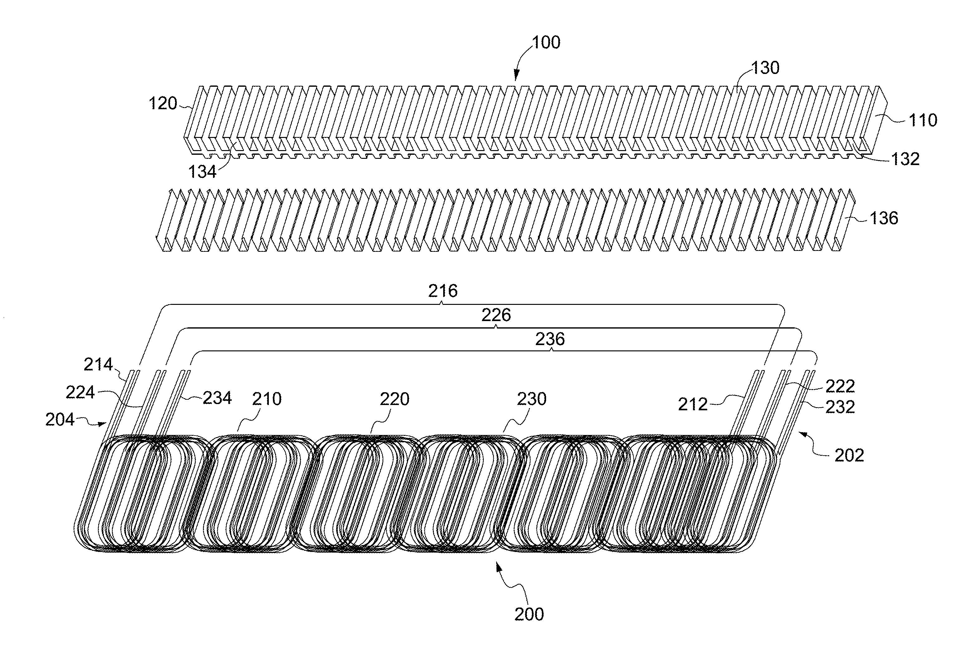
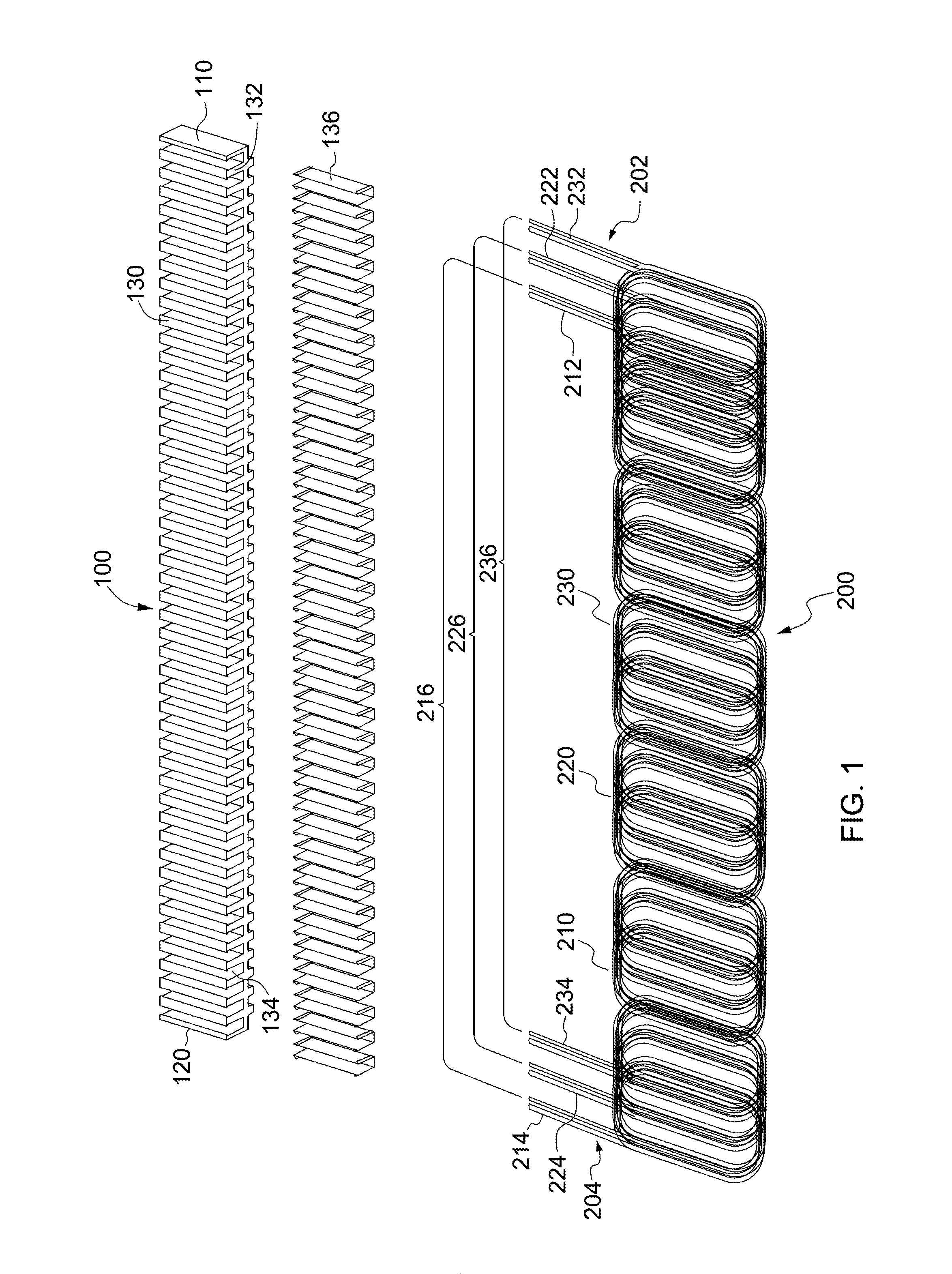
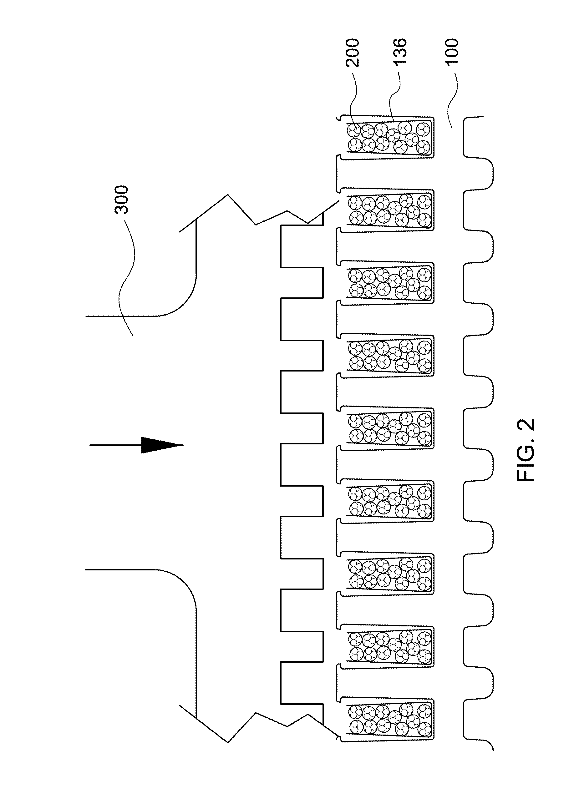
[0050]FIG. 1 is a schematic three-dimensional exploded view of an elongated stator of an alternator according to the present invention. As shown in FIG. 1, the elongated stator of an alternator according to the present invention mainly has an elongated stator body 100, the elongated stator body 100 has a first end 110 and a second end 120, and is convexly provided with a plurality of parallel teeth 132 on a first side 130, and a groove 134 is formed between the adjacent teeth 132 so that the grooves 134 also show a parallel architecture. In a preferred embodiment of the present invention, the elongated stator body 100 is formed by materials which can maintain electrical and magnet...


PUM


Abstract

The present invention relates to a stator of an alternator, providing an elongated stator body having a plurality of parallel grooves, winding a plurality of wires in the plurality of different grooves, and then rolling the elongated stator body wound with the wires into an annular shape to form an annular stator.

Description

CROSS-REFERENCE TO RELATED APPLICATIONS[0001]This application claims the benefit of priority to each of the following commonly-owned applications, each of which is herein incorporated by reference in their entirety for all purposes:[0002]U.S. patent application Ser. No. 13 / 753,554, filed Jan. 30, 2013, entitled “Annular-Shaped Stator Structure and Method of Manufacture,” and[0003]TW patent application no. 103 103 638, filed Jan. 29, 2014, entitled “Stator of an Alternator.”BACKGROUND OF THE INVENTION[0004]The present invention relates to a stator of an alternator, and in particular, to a stator of an alternator of automobiles.[0005]The alternator is one kind of generator and can convert mechanical energy to electrical energy in a form of alternating current (AC). A vehicle alternator converts mechanical energy produced by an engine to electrical energy for charging a battery so as to supply electrical power to other electrical appliances in the vehicle and to activate a motor to dri...

Claims


Application Information

Patent Timeline
IPC IPC(8): H02K1/16H02K3/30H02K1/02H02K3/34H02K3/12
CPCH02K1/16H02K1/02H02K3/345H02K3/30H02K3/12H02K15/024H02K15/0478
Inventor WANG, CHUN-YUANCHANG, CHIH-CHIN
Owner VICTORY INDAL
Why Eureka
Try Eureka