Power conversion apparatus and high-voltage DC transmission system

a technology of dc transmission system and power conversion apparatus, which is applied in the direction of power conversion system, electrical power transfer ac network, electrical apparatus, etc., can solve the problems of dc fault current flow and current flow caused by current, and achieve the effect of reducing the zero-phase dc curren

Active Publication Date: 2014-07-31
HITACHI LTD
View PDF10 Cites 22 Cited by
  • Summary
  • Abstract
  • Description
  • Claims
  • Application Information

AI Technical Summary

Benefits of technology

[0011]The present invention has been made in order to solve the problems described above, and it is therefore an object of the present invention to provide a power conversion apparatus which is capable of reducing a zero-phase DC current which is caused to flow into an AC grid side even when a grounding / short-circuiting fault of a DC transmission line is generated, and a high-voltage DC transmission system.
[0014]As set forth hereinabove, according to the present invention, it is possible to reduce the zero-phase DC current which is caused to flow into the AC grid in the phase of the grounding or short-circuiting fault of the DC transmission line in the HVDC.

Problems solved by technology

When a grounding or short-circuiting fault is generated in the DC transmission line of the HVDC, a DC fault current is caused to flow through the transformers arms and the secondary windings of the transformers.
In general, in the transformer connected to an ultrahigh-voltage AC grid, for example, the windings connected to the ultrahigh-voltage AC grid are wound in the form of Y-connection and a neutral point of the Y-connection is grounded in many cases, However, there is caused a problem that when the DC fault is generated, the DC fault current is caused to flow as a zero-phase DC current into the primary windings of the transformer, that is, into the AC grid side as well in some cases.

Method used


Image

  • Power conversion apparatus and high-voltage DC transmission system
  • Power conversion apparatus and high-voltage DC transmission system
  • Power conversion apparatus and high-voltage DC transmission system

Examples


first embodiment

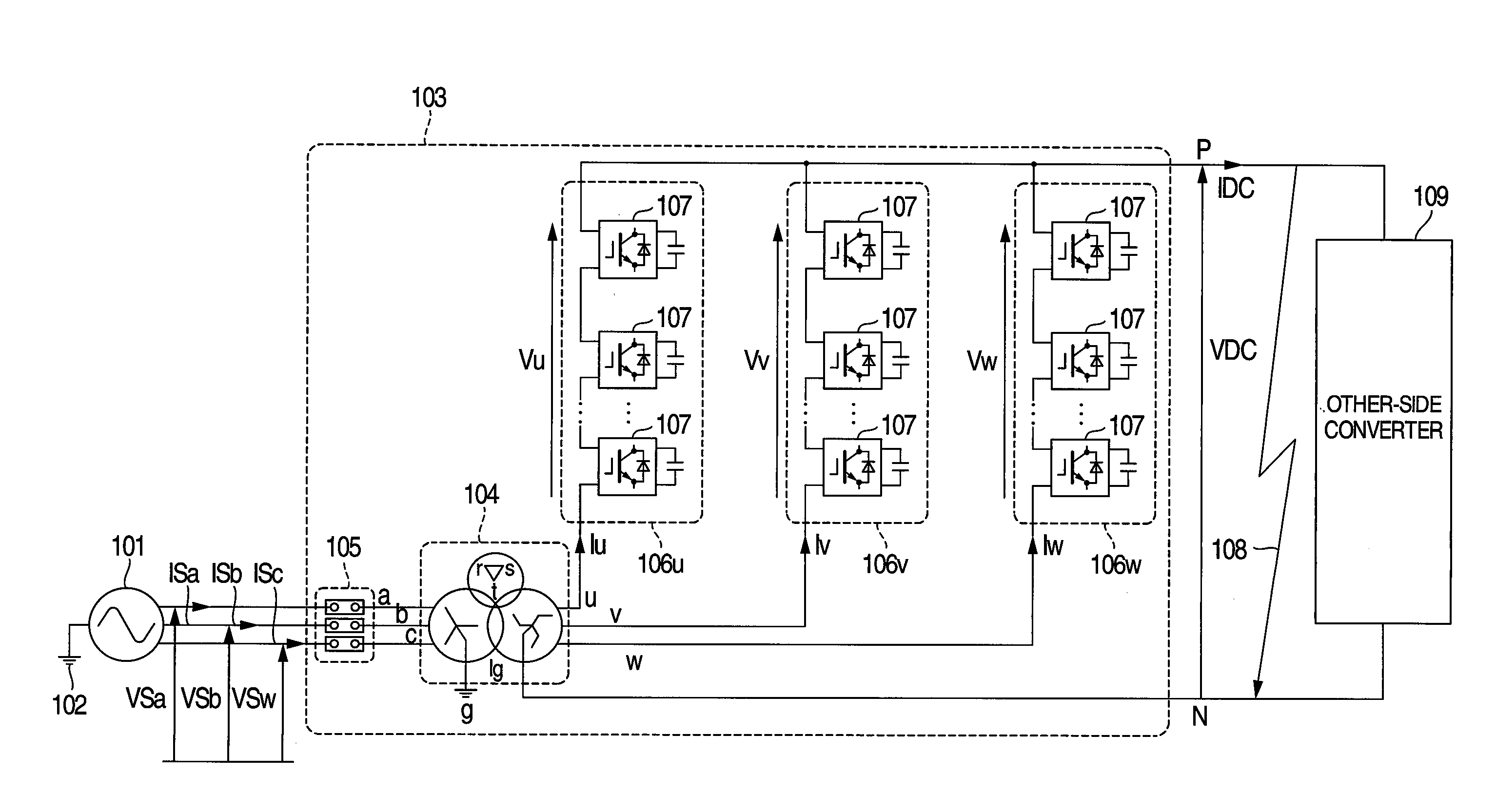
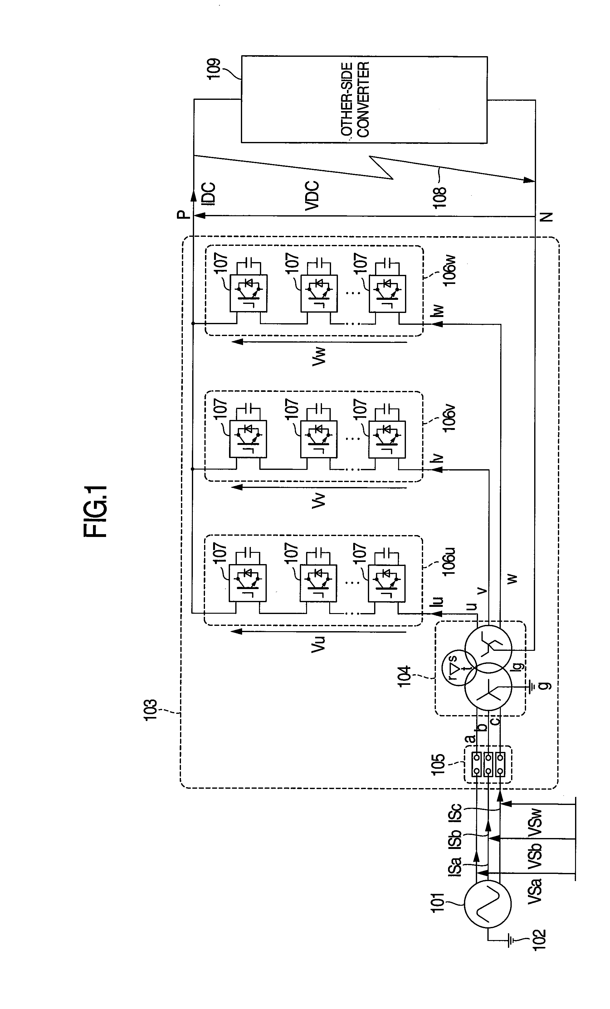
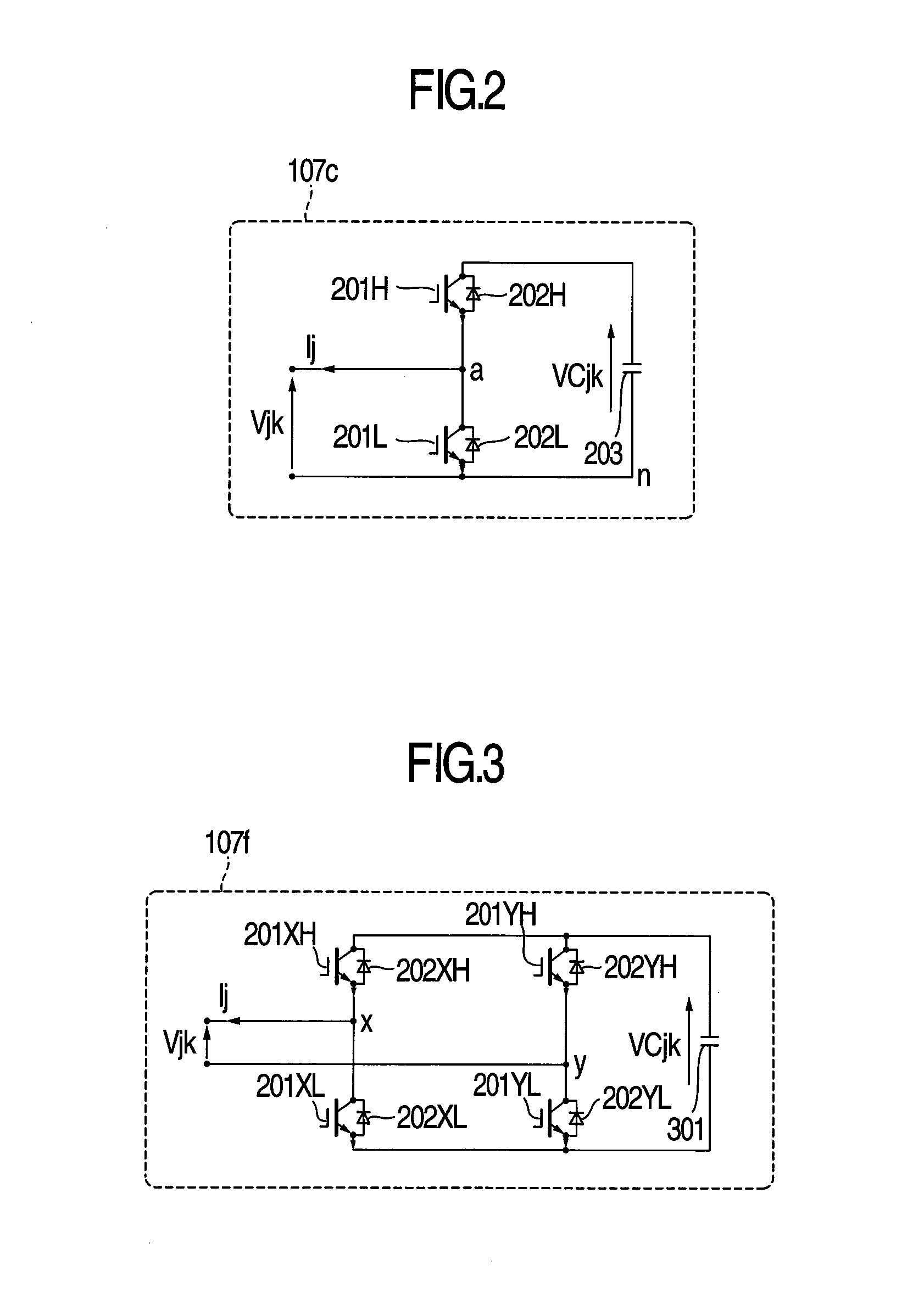
[0030]Hereinafter, a power conversion apparatus according to a first embodiment of the present invention will be described. The power conversion apparatus of the first embodiment is a power conversion apparatus as will be described below. That is to say, a bidirectional chopper circuit is used as a unit converter. Three circuits in which three converter arms configured by connecting plural bidirectional chopper circuits in series with one another, and three second windings of a transformer are connected in series with one another are connected in parallel with one another. In this case, one end of a parallel connection point is used as a DC positive side terminal, and the other end of the parallel connection point is used as a DC negative side terminal. Also, the primary windings of the transformer are connected to a three-phase power system, and tertiary windings of the transformer are wound in the form of Δ-connection.

[0031]In addition, the power conversion apparatus of the first ...

second embodiment

[0137]Hereinafter, a power conversion apparatus according to a second embodiment of the present invention will be described.

[0138]The power conversion apparatus of the second embodiment is a power conversion apparatus as will be described below. That is to say, a bidirectional chopper circuit is used as a unit converter. Also, three circuits in each of which three conversion arms configured by connecting plural bidirectional chopper circuits in series with one another, and three secondary windings of a transformer are connected in series with each other are connected in parallel with each other. One end of a parallel connection point is used as a DC positive side terminal, and the other end thereof is used as a DC negative side terminal. Also, primary windings of the transformer are connected to a three-phase power grid, and tertiary windings of the transformer are wound in the form of Δ-connection.

[0139]In addition, the power conversion apparatus of the second embodiment has a conf...

third embodiment

[0167]Hereinafter, a power conversion apparatus according to a third embodiment of the present invention will be described.

[0168]The power conversion apparatus of the third embodiment is a power conversion apparatus as will be described below. That is to say, a bidirectional chopper circuit is used as a unit converter. Also, three circuits in each of which three conversion arms configured by connecting plural bidirectional chopper circuits in series with one another, and three secondary windings of a transformer are connected in series with each other are connected in parallel with each other. One end of a parallel connection point is used as a DC positive side terminal, and the other end thereof is used as a DC negative side terminal. Also, primary windings of the transformer are connected to a three-phase power grid, and tertiary windings of the transformer are wound in the form of Δ-connection.

[0169]In addition, the power conversion apparatus of the third embodiment has a configu...


PUM


Abstract

A power conversion apparatus including a three-phase transformer having at least four three-phase windings, and three converter arms each configured by connecting one or plural unit converters each including a switching device and an energy storage element in series. A power source or a load is connected to a first three-phase winding of the transformer, three series circuits which connects second and third three-phase windings of the transformer, and the converter arms in series with each other are connected in parallel, the parallel connection point is a DC terminal, and a magnitude relationship between a coupling coefficient of the first and second three-phase windings, and a coupling coefficient of the first three- and third three-phase windings is equal to a magnitude relationship between a coupling coefficient of the fourth and second three-phase windings, and a coupling coefficient of the fourth and the third three-phase windings.

Description

BACKGROUND OF THE INVENTION[0001]The present invention relates to a power conversion apparatus for converting an AC electric power into a DC electric power or converting a DC electric power into an AC electric power, and a power conversion system. More particularly, the invention relates to a power conversion apparatus which includes an arm configured by connecting one or plural unit converters in series with one another, and thus is suitable for converting an electric power, and a high-voltage DC transmission system.[0002]In recent years, a technique for converting an AC electric power into a DC electric power or converting a DC electric power into an AC electric power has been used in many cases. As far as this sort of apparatus, an apparatus which utilizes a unit converter is known. This apparatus is such that plural unit converters are connected in series with one another, and a semiconductor switching device is operated for an energy storage element in each of the unit converte...

Claims


Application Information

Patent Timeline
Patent Type & Authority Applications(United States)
IPC IPC(8): H02M7/797
CPCH02M7/797H02J3/36Y02E60/60H02M7/4835
Inventor INOUE, SHIGENORIKATOH, SHUJIKIYOFUJI, YASUHIROKADOWAKI, MAKOTOFUJITA, HIROYUKIOGATA, HIDEKI
Owner HITACHI LTD
Why Eureka
Try Eureka