Terminal, base station, communication system, and communication method

a communication system and terminal technology, applied in the direction of wireless communication, wireless communication, transmission path division, etc., can solve the problem that no pucch resource can be made available for two terminals, and achieve the effect of efficient specification

Active Publication Date: 2014-07-31
SHARP KK
View PDF8 Cites 20 Cited by
  • Summary
  • Abstract
  • Description
  • Claims
  • Application Information

AI Technical Summary

Benefits of technology

[0025]According to the present invention, in a wireless communication system in which a base station and a terminal communicate with each other, even in the case where the base station reports control information for the terminal not only via a physical downlink control channel but also via an enhanced physical downlink control channel, a physical uplink control channel resource can be efficiently specified.

Problems solved by technology

In addition, no PUCCH resource can be made to be available for two terminals (see NPL 1 and NPL 2).

Method used


Image

  • Terminal, base station, communication system, and communication method
  • Terminal, base station, communication system, and communication method
  • Terminal, base station, communication system, and communication method

Examples


first embodiment

[0055]Hereinafter, a first embodiment of the present invention will be described. A communication system in the first embodiment includes a base station (a base station device, a downlink transmitter, an uplink receiver, and eNodeB) and a terminal (a terminal device, a mobile station device, a downlink receiver, an uplink transmitter, and UE).

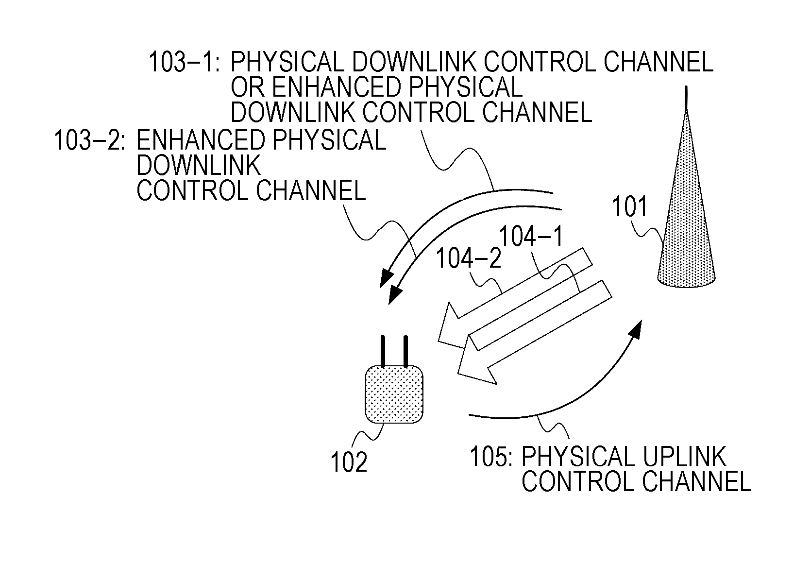
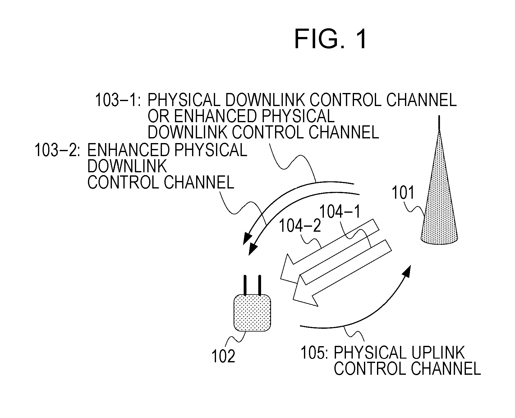
[0056]FIG. 1 is a diagram illustrating an example of the configuration of the communication system according to the first embodiment. In FIG. 1, a base station 101 delivers to a terminal 102 control information regarding downlink transmit data 104-1 and 104-2 via a PDCCH and / or an enhanced physical downlink control channel (E-PDCCH: Enhanced-PDCCH) 103-1 and an E-PDCCH 103-2, which are control channels used for dynamical signaling. Here, the downlink transmit data 104-1 and 104-2 are arranged in physical downlink shared channels (PDSCH; Physical Downlink Shared CHannel) in accommodation cells (a primary cell (PCell) and a secondary cell (SCell)...

second embodiment

[0131]In the first embodiment described above, the case in which an uplink control channel is dynamically allocated to the terminal has been described. Hereinafter, in a second embodiment of the present invention, the case in which an uplink control channel is semi-statically allocated to the terminal will be described. A communication system in this embodiment can use a configuration that is the same as or similar to that of the communication system illustrated in FIG. 1. In addition, the block configurations of the base station 101 and the terminal 102 in this embodiment can use configurations that are the same as or similar to the block configurations illustrated in FIG. 4 and FIG. 5.

[0132]FIG. 21 is a diagram illustrating the configuration of an E-PDCCH and allocation of PUCCH resources. An E-PDCCH illustrated in FIG. 21 illustrates the configuration of an E-PDCCH and allocation of PUCCH resources in the case where cross interleaving is adopted. The configuration of the E-PDCCH ...

third embodiment

[0154]In the first embodiment described above, the case in which an uplink control channel is dynamically allocated to the terminal has been described. Hereinafter, in a third embodiment of the present invention, the case in which, among semi-statically configured uplink control channels, a dynamically-specified uplink control channel is allocated to the terminal will be described. A communication system in this embodiment can use a configuration that is the same as or similar to that of the communication system illustrated in FIG. 1. In addition, the block configurations of the base station 101 and the terminal 102 in this embodiment can use configurations that are the same as or similar to the block configurations illustrated in FIG. 4 and FIG. 5.

[0155]FIG. 25 is a diagram illustrating the configuration of an E-PDCCH and allocation of PUCCH resources. Note that an E-PDCCH illustrated in FIG. 25 illustrates the configuration of an E-PDCCH and allocation of PUCCH resources in the ca...


PUM


Abstract

In a terminal that communicates with a base station, in the case where a physical downlink control channel or an enhanced physical downlink control channel, which is associated with a physical downlink shared channel on a first cell, and an enhanced physical downlink control channel associated with a physical downlink shared channel on a second cell are detected, one physical uplink control channel resource is selected from a physical uplink control channel resource configured for the physical downlink shared channel on the first cell and a physical uplink control channel resource configured for the physical downlink shared channel on the second cell.

Description

TECHNICAL FIELD[0001]The present invention relates to a terminal, a base station, a communication system, and a communication method.BACKGROUND ART[0002]In wireless communication systems such as LTE (Long Term Evolution) and LTE-A (LTE-Advanced) proposed by 3GPP (Third Generation Partnership Project), and Wireless LAN and WiMAX (Worldwide Interoperability for Microwave Access) proposed by IEEE (The Institute of Electrical and Electronics engineers), a base station (a base station device, a downlink transmitter, an uplink receiver, and eNodeB) and a terminal (a terminal device, a mobile station device, a downlink receiver, an uplink transmitter, and UE) have a plurality of transmit / receive antennas, and, with the use of MIMO (Multi Input Multi Output) technology, data signals are spatially multiplexed, thereby realizing high-speed data communication. In addition, high frequency usage efficiency is particularly realized in LTE and LTE-A by using the OFDM (Orthogonal Frequency Division...

Claims


Application Information

Patent Timeline
Patent Type & Authority Applications(United States)
IPC IPC(8): H04L5/00
CPCH04L5/0053H04L5/001H04L1/1861H04L27/2602H04L5/0055H04L1/1854H04J13/0003
Inventor NOGAMI, TOSHIZOAIBA, TATSUSHINAKASHIMA, DAIICHIROSHIMEZAWA, KAZUYUKIIMAMURA, KIMIHIKO
Owner SHARP KK
Why Eureka
Try Eureka