Underwater optical communication system

Active Publication Date: 2014-07-31
MASSACHUSETTS INST OF TECH
View PDF9 Cites 57 Cited by
  • Summary
  • Abstract
  • Description
  • Claims
  • Application Information

AI Technical Summary

Benefits of technology

[0006]In an untethered environment, a need exists to collect data from a variety of sensors on the sea floor using an unmanned underwater vehicle (UUV). The UUV is required to locate sensors to position itself to reliably receive transmitted dat

Problems solved by technology

Such use of tethers restricts mobility and limits the ocean depths that can be explored due to limitations on the length of the tether.
Acoustic communication enables wireless transmission of information underwater but is limited by low bandwidth and

Method used


Image

  • Underwater optical communication system
  • Underwater optical communication system
  • Underwater optical communication system

Examples


Embodiment Construction

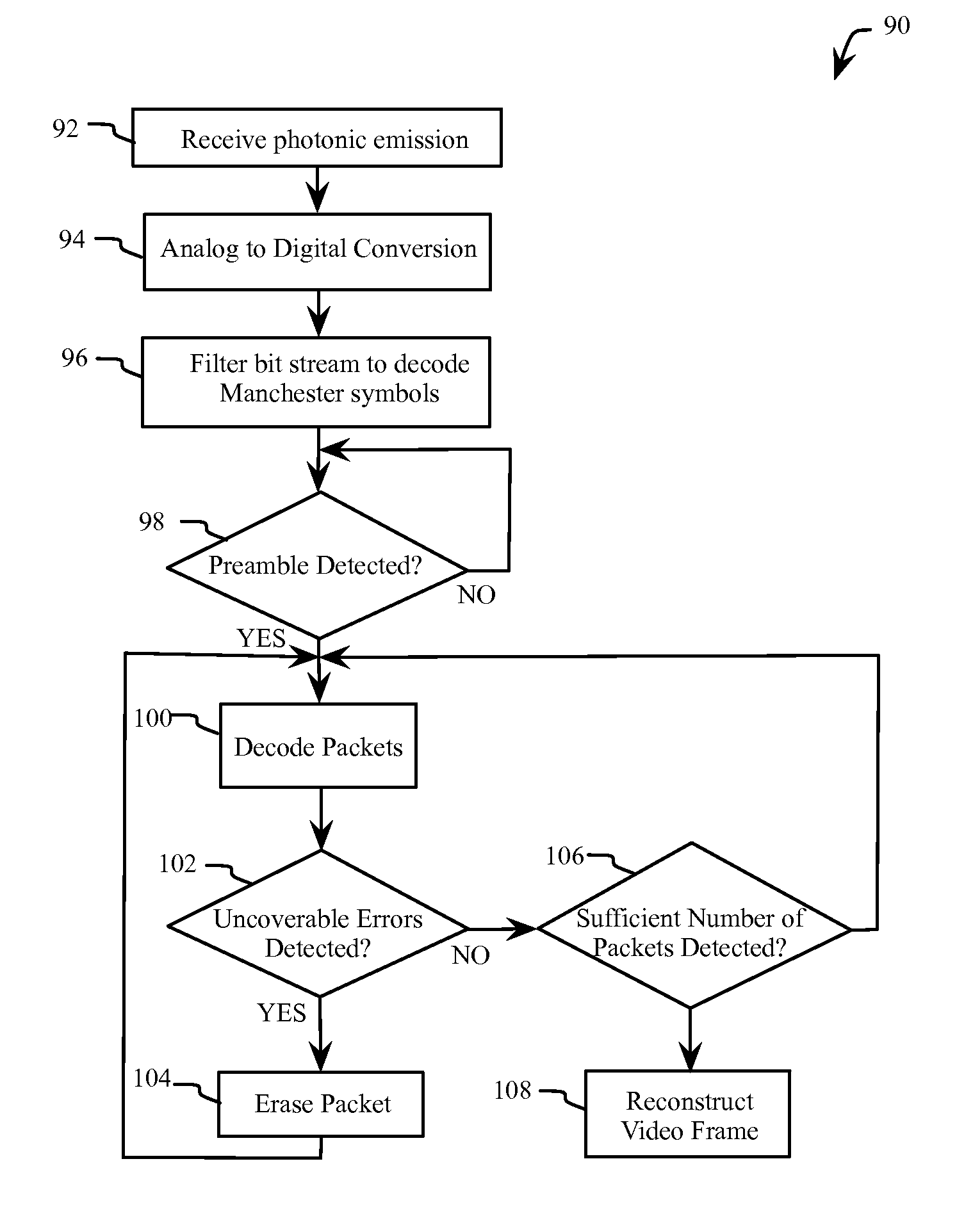
[0024]Embodiments of methods and systems described herein provide for high bandwidth and low latency transmission of data in a lossy underwater environment. In one example, high quality video is supported with 98 percent success at ranges within 25 yards, and with acceptable quality up to 40 yards. In another example communication latencies of 100 ms are achieved, thus enabling teleoperation between mobile UUVs and a plurality of sensors. Embodiments described herein employ a two-layer digital encoding scheme designed for error-resistant communication through a unidirectional channel for an efficient communication infrastructure. In other embodiments, bidirectional communication between a UUV and a sensor enables adaptive control of the transmission properties (e.g. packet size) to optimize transmission latency and frame success rate (e.g. a measure of reliability).

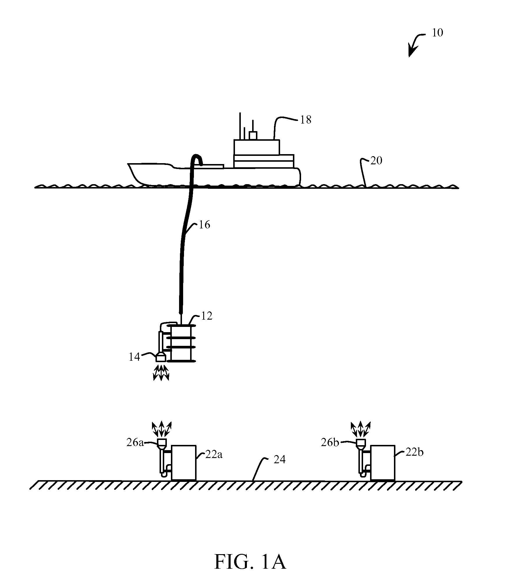
[0025]FIG. 1A illustrates an embodiment of an underwater optical communication system 10 with a tethered optical receiv...


PUM


Abstract

A method of optical underwater communications comprises applying a Fountain code to a plurality of data blocks. A sequence of optical data packets is transmitted through an underwater communications channel. Each optical data packet comprises one of the plurality of data blocks preceded by a preamble. The sequence of optical data packets transmitted through the underwater communication channel is received to generate a sequence of received data packets. The sequence of received data packets is sampled with the sampling clock to recover the plurality of data blocks.

Description

CROSS-REFERENCE TO RELATED APPLICATIONS[0001]This application is a utility application claiming priority to co-pending U.S. Provisional Application Ser. No. 61 / 670,734 filed on Jul. 12, 2012 entitled “UNDERWATER OPTICAL COMMUNICATIONS METHODS AND SYSTEMS,” the entirety of which is incorporated by reference herein.GOVERNMENT RIGHTS IN THE INVENTION[0002]This invention was made with government support under Contract No. N00014-09-1-1031 awarded by the U.S. Navy and under Grant No. IIS1117178 awarded by the National Science Foundation. The government has certain rights in the invention.FIELD OF THE INVENTION[0003]The present invention relates generally to wireless communication. More specifically, the invention relates to underwater optical wireless communication to support high quality data transmission and object localization.BACKGROUND[0004]Approximately 70% of the Earth's surface is covered by water, yet much of the subsea world remains largely unexplored. Ocean observatories curre...

Claims


Application Information

Patent Timeline
IPC IPC(8): H04B10/80H04L7/00
CPCH04B13/02H04B10/80H04L7/0075
Inventor DONIEC, MAREK W.RUS, DANIELA
Owner MASSACHUSETTS INST OF TECH
Why Eureka
Try Eureka