
Fastener Stringer and Fastener Chain, and Manufacturing Method of Fastener Chain

a technology of fastener stringer and fastener chain, which is applied in the manufacture of snap fasteners, buckles, manufacturing tools, etc., can solve the problems of low durability of printed patterns, and achieve the effects of improving the fixability of ink, expanding the design range of slide fasteners, and improving the adhesiveness between the metal body of the fastener element and the printable resin layer

Active Publication Date: 2014-08-07
YKK CORP
View PDF22 Cites 3 Cited by
  • Summary
  • Abstract
  • Description
  • Claims
  • Application Information

AI Technical Summary

Benefits of technology

The invention is a fastener stringer that has a printable resin layer on its metallic fastener element, allowing for stable ink fixation using inkjet printing. The pattern can be formed on the inner side of the fastener tape, expanding the design range of the slide fastener. An adhesive layer made of epoxy resin is used to improve the adhesiveness of the printing pattern. An auxiliary resin layer made of acrylic resin or acryl-urethane resin is added for better ink fixability. The technical effects of the invention include stable ink fixation, expanded design range, and improved adhesiveness.

Problems solved by technology

As a result, for example, when a printing surface by the inkjet method contacts or grazes the other member, the ink is easily separated from the surface, and as a result, durability of a printed pattern is low.

Method used


Image

  • Fastener Stringer and Fastener Chain, and Manufacturing Method of Fastener Chain
  • Fastener Stringer and Fastener Chain, and Manufacturing Method of Fastener Chain
  • Fastener Stringer and Fastener Chain, and Manufacturing Method of Fastener Chain

Examples


first embodiment

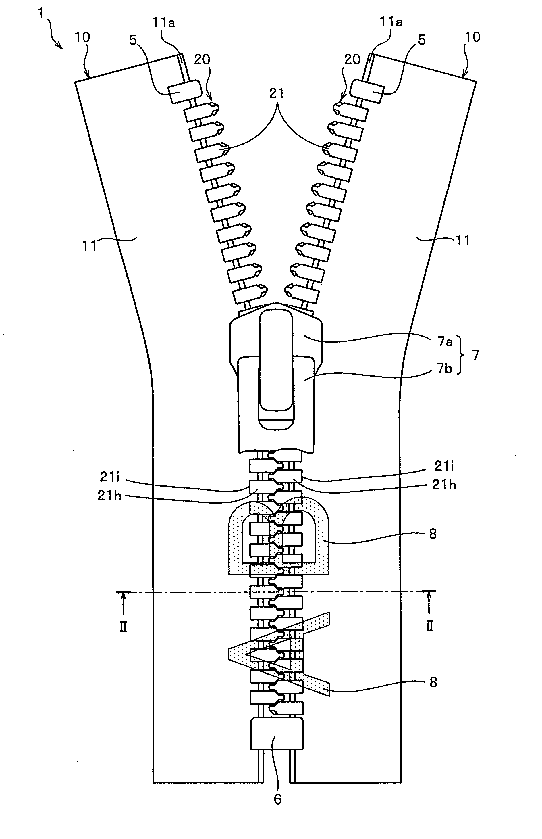
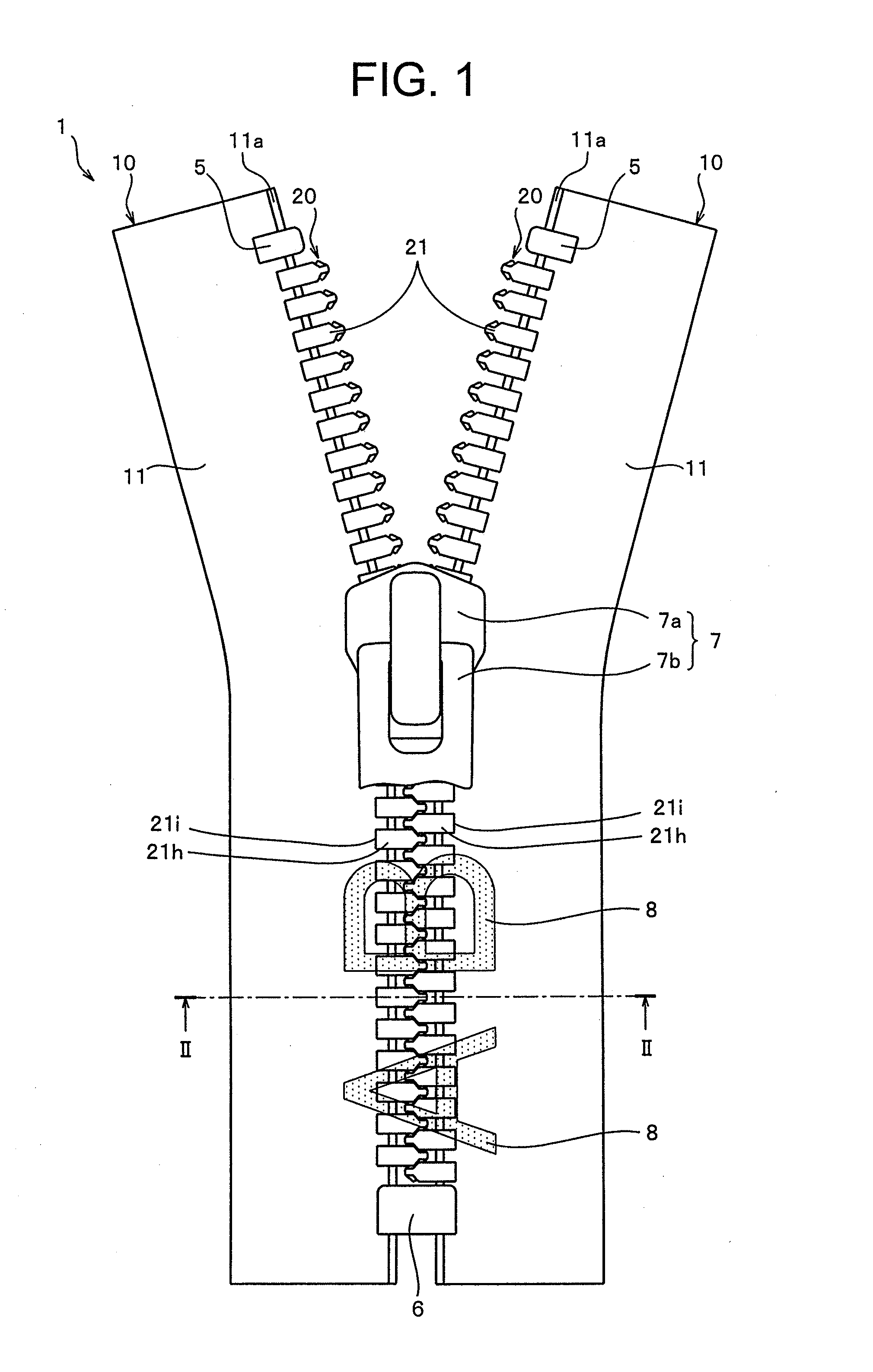
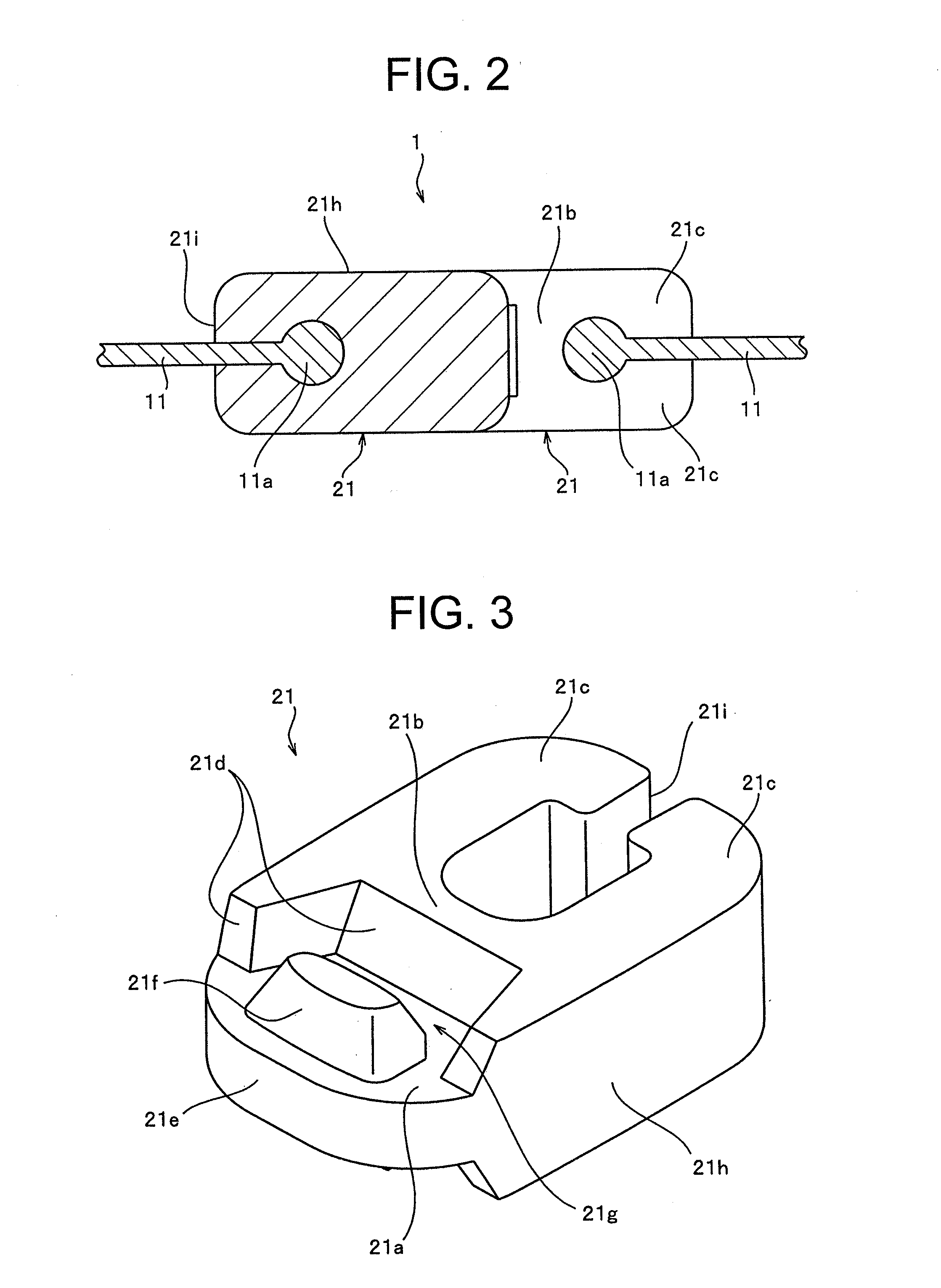
[0062]FIG. 1 is a front view of a slide fastener according to a first embodiment of the invention. FIG. 2 is a cross-sectional view of line II-II illustrated in FIG. 1. Further, FIG. 3 is a perspective view illustrating a fastener element arranged in the slide fastener. In addition, FIG. 4 and FIG. 5 are cross-sectional views illustrating basic configurations of layers formed on an exposed surface and an inner surface of the fastener element, respectively. In FIG. 4 and FIG. 5, each layer is schematically illustrated to have a certain amount of thickness in order to easily show a feature of the invention.

[0063]Further, in the following description, a front and rear direction represents a longitudinal direction of the fastener tape, and in particular, a direction to slide a slider to couple left and right element rows is set as a front direction, and a direction to slide the slider to separate the left and right element rows is set as a back direction. In addition, a left and right d...

second embodiment

[0121]FIG. 8 is a cross-sectional view illustrating a basic configuration of a layer formed on an exposed surface and an inner surface of a fastener element of a slide fastener according to a second embodiment.

[0122]In the slide fastener according to the second embodiment, a printable resin layer 43 is formed on an entire surface of each fastener element 41 and thereafter, printing by an inkjet method is carried out on the fastener element 41 where the printable resin layer 43 is formed. That is, in the second embodiment, a configuration of the layer formed in the fastener element 41 is different from that of the fastener element 41 of the first embodiment, and a minimum configuration in which the printing by the inkjet method is carried out on the metallic fastener element 41 is described.

[0123]Further, in the second embodiment, the slide fastener of the embodiment is substantially the same as the slide fastener according to the first embodiment other than that the configuration of...


PUM

PropertyMeasurementUnit
thicknessaaaaaaaaaa
thicknessaaaaaaaaaa
reflectivityaaaaaaaaaa

Abstract

The fastener stringer is arranged with at least one printable resin layer to which ink can be fixed on the entire surface of fastener elements. Printing by an inkjet method is carried out at least on the exposed surfaces exposed on the first tape surface side in the tape front- and back direction of the fastener elements, the inner surfaces of the first tape surface side facing the tape inward side, along with the first tape surface of the fastener tape. A desired pattern can thereby be stably formed not only on the fastener tape and the exposed surfaces of the fastener elements, but can also be formed on the inner surfaces of the fastener elements. Therefore, a pattern can be formed in a continuous manner on the fastener tape and the fastener elements, and decorativeness and design unattainable in the past can be obtained.

Description

TECHNICAL FIELD[0001]The invention relates to a fastener stringer and a fastener chain in which a plurality of metallic fastener elements is attached to a tape side edge portion of a fastener tape and printing by an inkjet method is carried out, and a method for manufacturing the fastener chain.BACKGROUND ART[0002]In general, a slide fastener is manufactured by configuring a fastener stringer by attaching a synthetic resin or a metal fastener element to an opposing side edge portion of a woven or knitted fastener tape, and further, to one set of two fastener stringers that are obtained, a slider is slidably attached to element rows of left and right fastener stringers. In the slide fastener, the opposing fastener elements are coupled with and separated from each other by sliding the slider along the element rows.[0003]Conventionally, various designs have been carried out in clothes or bags using the slide fastener, and further, new designs are required in order to further enhance va...

Claims


Application Information

Patent Timeline
Patent Type & Authority Applications(United States)
IPC IPC(8): A44B19/34A44B19/46
CPCA44B19/46A44B19/34Y10T24/25Y10T29/49984A44B19/02A44B19/42
Inventor HAYASHI, AKIOMARUOKA, KANAEKURATA, TAKESHIGETAKAMOTO, AYA
Owner YKK CORP
Learn More