

Vehicle engine control device
- Summary
- Abstract
- Description
- Claims
- Application Information
AI Technical Summary
Benefits of technology
Problems solved by technology
Method used
Image

Examples
embodiment
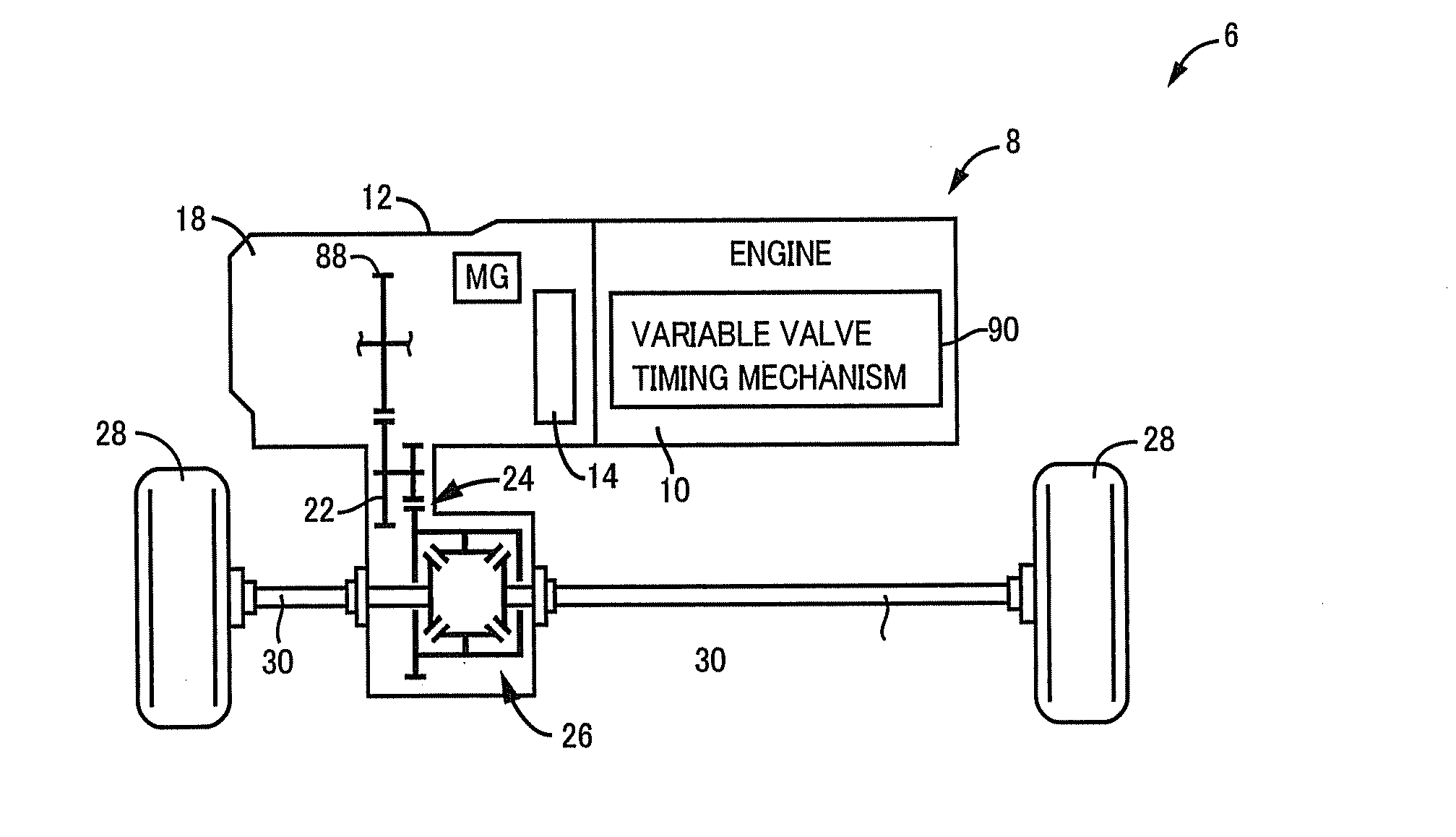
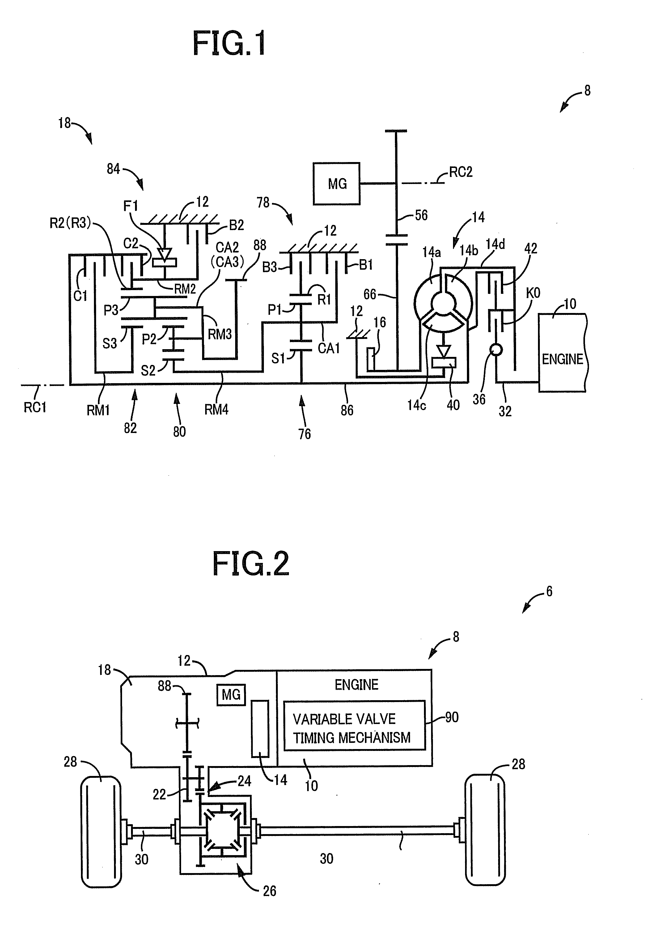
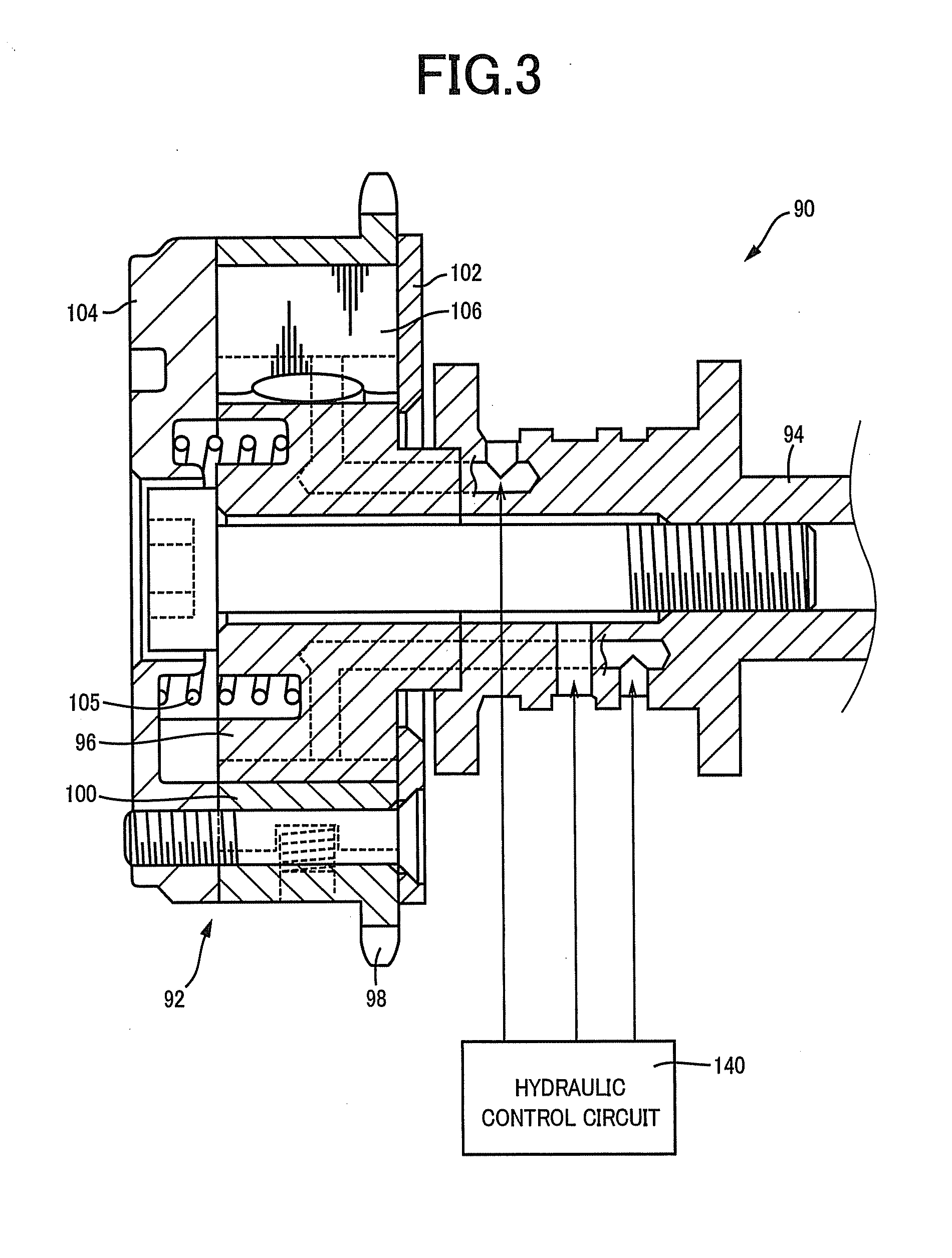
[0024]FIG. 1 is a schematic for explaining a configuration of a main portion of a vehicle drive device 8 to which a control device of a vehicle engine including a variable valve timing mechanism of the present invention is preferably applied. FIG. 2 is a diagram for explaining a power transmission path from the vehicle drive device 8 to drive wheels 28.
[0025]As depicted in FIGS. 1 and 2, the vehicle drive device 8 has a case 12 as a non-rotating member attached to a vehicle body by bolts etc., includes an engine intermittent clutch K0, a torque converter 14, a hydraulic pump 16, and an automatic transmission 18 in the case 12 on a first axial center RC1 in order, i.e., in series, from an engine 10 side, and includes an electric motor MG rotationally driven around a second axial center RC2 parallel to the first axial center RC1. As depicted in FIG. 2, the drive device 8 includes a counter driven gear 22 meshed with an output gear 88 that is an output rotating member of the automatic ...
PUM
 Abstract
Description
Claims
Application Information