
Method and system for sensing light reflective surfaces in a reflective photo-electric sensing system

a light reflective surface and sensing system technology, applied in the field of light reflective photoelectric sensing system, can solve the problem of wrong classification of objects as reflectors, and achieve the effect of increasing reliability and increasing sensing system reliability

Inactive Publication Date: 2014-08-07
FRABA
View PDF2 Cites 2 Cited by
  • Summary
  • Abstract
  • Description
  • Claims
  • Application Information

AI Technical Summary

Benefits of technology

The patent text describes a system for improving the detection of objects in a space using electrical signals. By analyzing the signals in both the near and far fields, the system can determine if an object is present and create an actuation signal accordingly. The system can also use a polarization filter to distinguish between reflective objects and the reflector. This helps to increase reliability and suppress ambient light, making it easier to detect objects. In summary, the system is designed to improve the accuracy and reliability of object detection in a space.

Problems solved by technology

This can lead to the object being wrongly classified as a reflector in the monitoring system.

Method used


Image

  • Method and system for sensing light reflective surfaces in a reflective photo-electric sensing system
  • Method and system for sensing light reflective surfaces in a reflective photo-electric sensing system
  • Method and system for sensing light reflective surfaces in a reflective photo-electric sensing system

Examples


Embodiment Construction

[0018]Reference will now be made in greater detail to a preferred embodiment of the invention, an example of which is illustrated in the accompanying drawings. Wherever possible, the same reference numerals will be used throughout the drawings and the description to refer to the same or like parts.

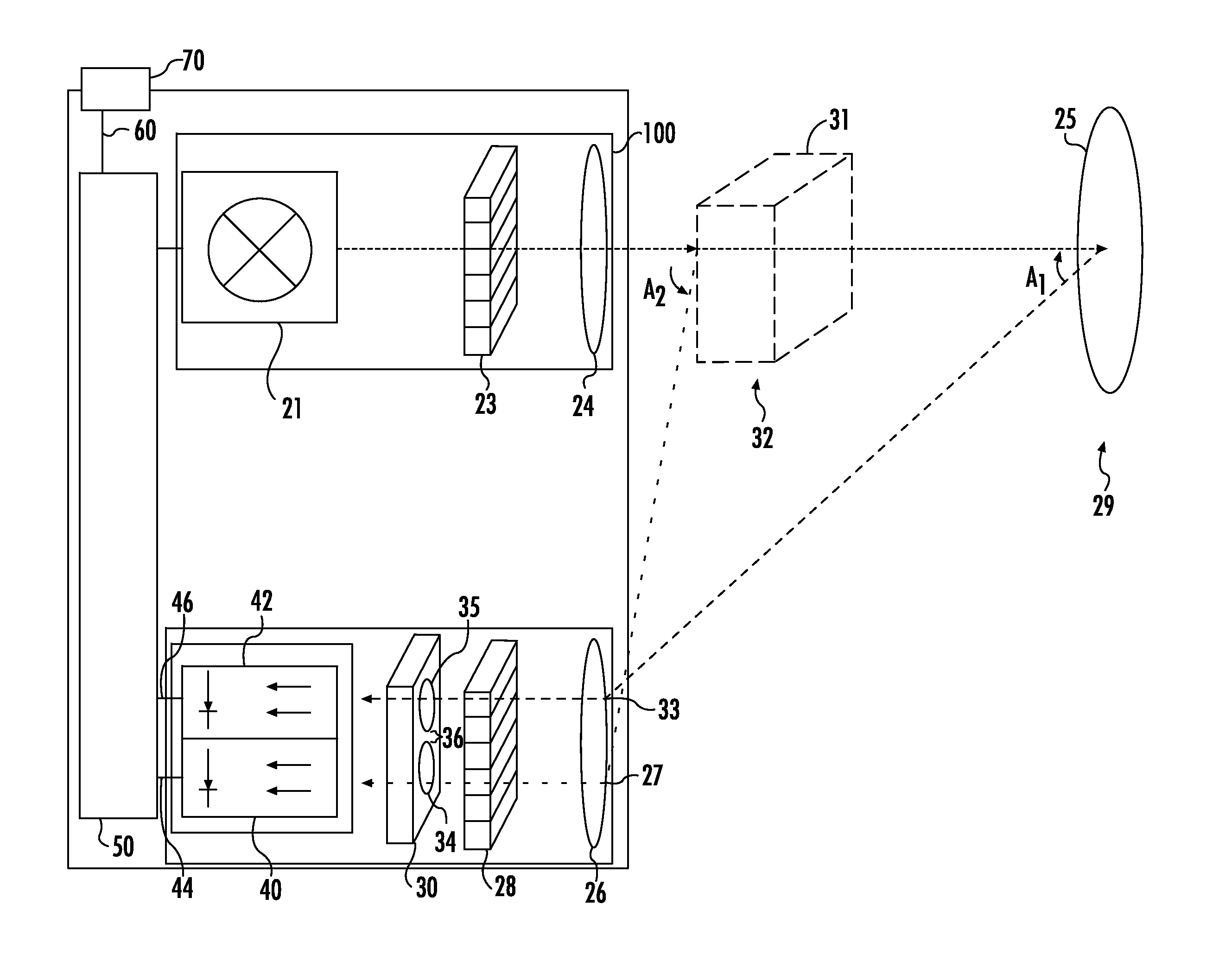
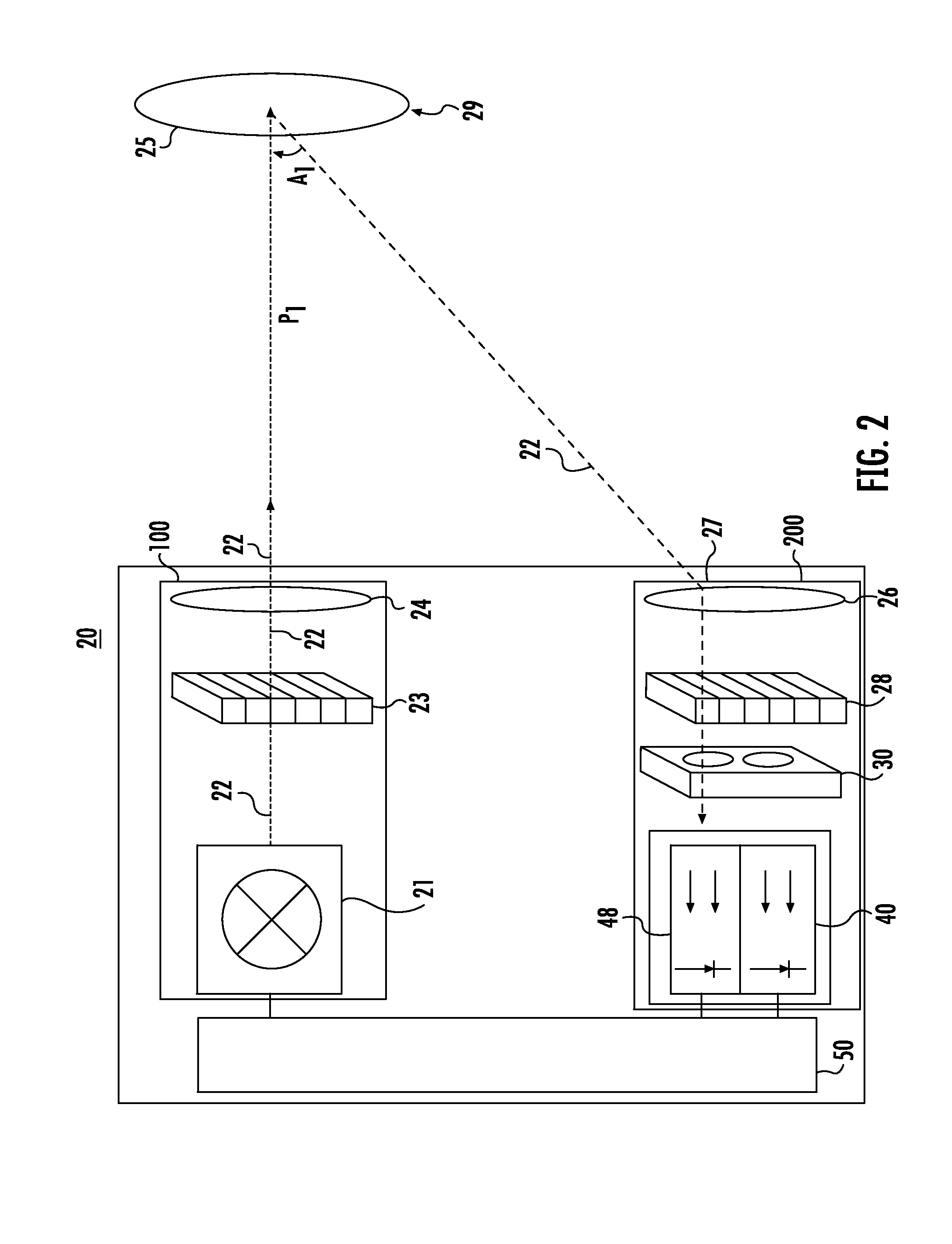
[0019]FIG. 2 is a schematic diagram of light reflective photo-electric sensing system 20, in accordance with the teachings of the present invention. Transmitter 21 of transmitter unit 100 transmits light 22 through transmitter polarization filter 23.

[0020]Transmitter 21 can be a transmit chip. For example, transmitter 21 can be a transmitting chip of a LED, a diode laser or a Vertical-Cavity Surface-Emitting Laser (VCSEL). Transmitter polarization filter 23 polarizes light 22. Light 22 from transmitter polarization filter 23 is transmitted to transmission lens 24. Light 22 is transmitted from transmitter lens 24 to reflector 25 if no object is present in path P1 of light 22.

[0021]Light 22 ...


PUM


Abstract

A reflective photo-electric sensing system includes a transmitter for the transmission of light and a reflector for reflecting the light. The reflector being positioned in a far field. A light channeling device receives reflected light from the far field or from a near field and channels the received reflected light to a near field receiver or a far field receiver dependent on an angle of the received reflected light. An electrical signal is generated at the near field receiver or the far field receiver. A controller evaluates the electrical signal of the near field receiver and the electrical signal of the far field receiver and generates an actuation signal dependent on the evaluation.

Description

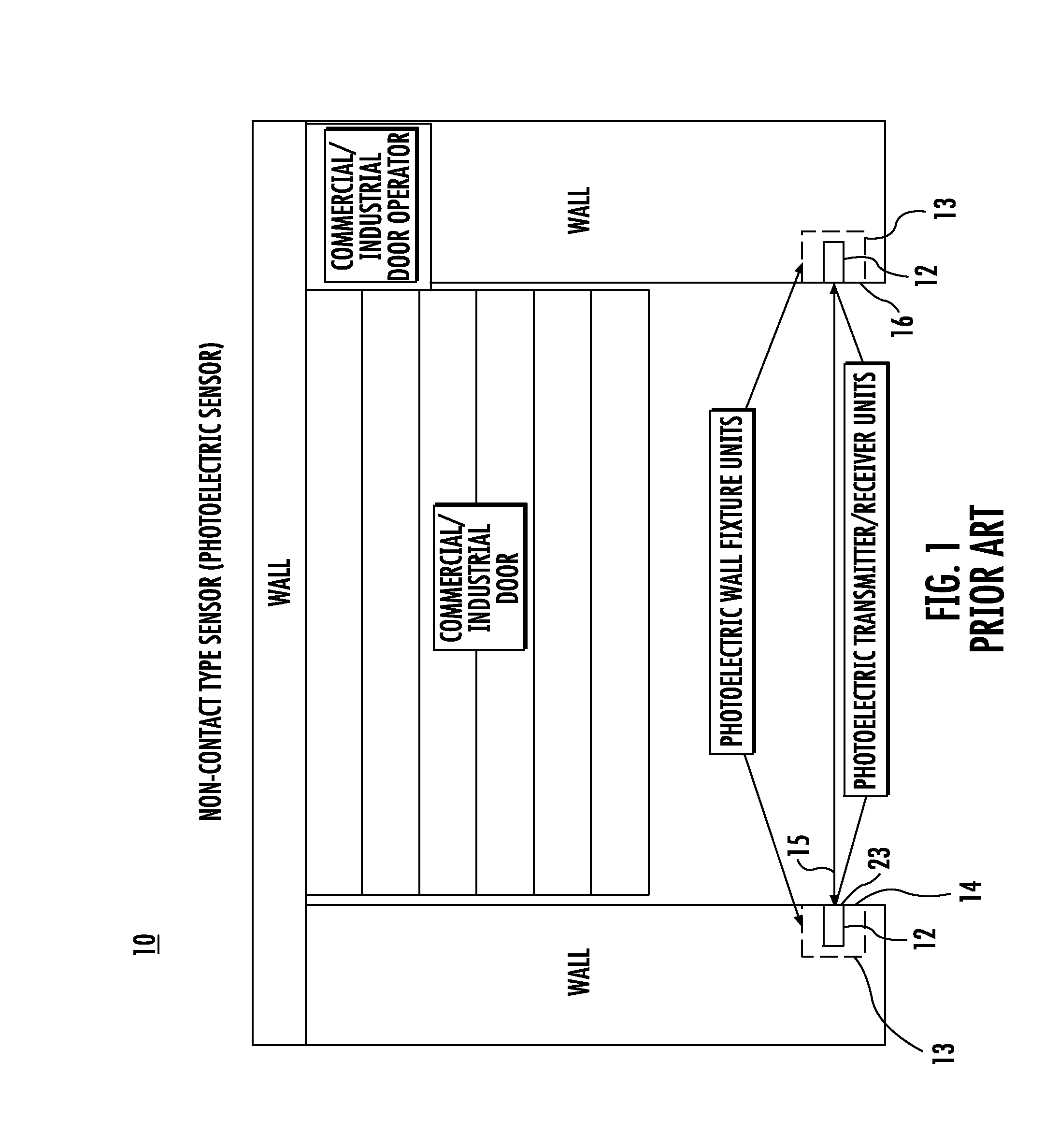
BACKGROUND OF THE INVENTION[0001]1. Field of the Invention[0002]The present invention relates to a light reflective photo-electric sensing system including a method and system for sensing objects, which can be light reflective surfaces, within the system and providing an actuation signal if objects are present. The method and system can be used in a non-contact type sensor entrapment protection system.[0003]2. Description of Related Art[0004]Non-contact type sensor entrapment systems are known. U.S. Patent Application Publication No. 2011-0049339-A1, hereby incorporated by reference into this application, describes a photo-electric eye safety system used in conjunction with a motorized barrier operator system having a primary photo-electric eye safety device, which includes a primary emitter mounted at one side of an opening enclosed by the barrier, and a primary receiver mounted on another side of the opening and aligned to receive a beam from said primary emitter. A controller mon...

Claims


Application Information

Patent Timeline
IPC IPC(8): G01V8/22
CPCG01V8/22
Inventor QUAISER, ANDRE
Owner FRABA
Learn More