Generator motor and electric vehicle using same

a generator motor and electric vehicle technology, applied in electric vehicle charging technology, transportation and packaging, cooling/ventilation arrangement, etc., to achieve the effect of reducing size, and enhancing the cooling

Active Publication Date: 2014-08-07
NIHON KENKI CO LTD +1
View PDF5 Cites 20 Cited by
  • Summary
  • Abstract
  • Description
  • Claims
  • Application Information

AI Technical Summary

Benefits of technology

[0014]According to the invention, the armature windings of the generator motor can be uniformly cooled down in the circumferential direction of the stator so that the cooling effect can be enhanced. In addition, when the generator motor is applied to an electric vehicle such as a hydraulic excavator, it is possible to more greatly enhance the cooling effect required under the condition that the generator motor is disposed in a small space in a high temperature environment and it is possible to contribute to both reduction in size and increase in output density.

Problems solved by technology

In addition, due to the configuration in which the electric motor is placed in a small space between the engine and the hydraulic pump, the electric motor inevitably has to be designed to achieve reduction in size and increase in output density (to be designed to achieve increase in output power per unit volume).

Method used


Image

  • Generator motor and electric vehicle using same
  • Generator motor and electric vehicle using same
  • Generator motor and electric vehicle using same

Examples


example 1

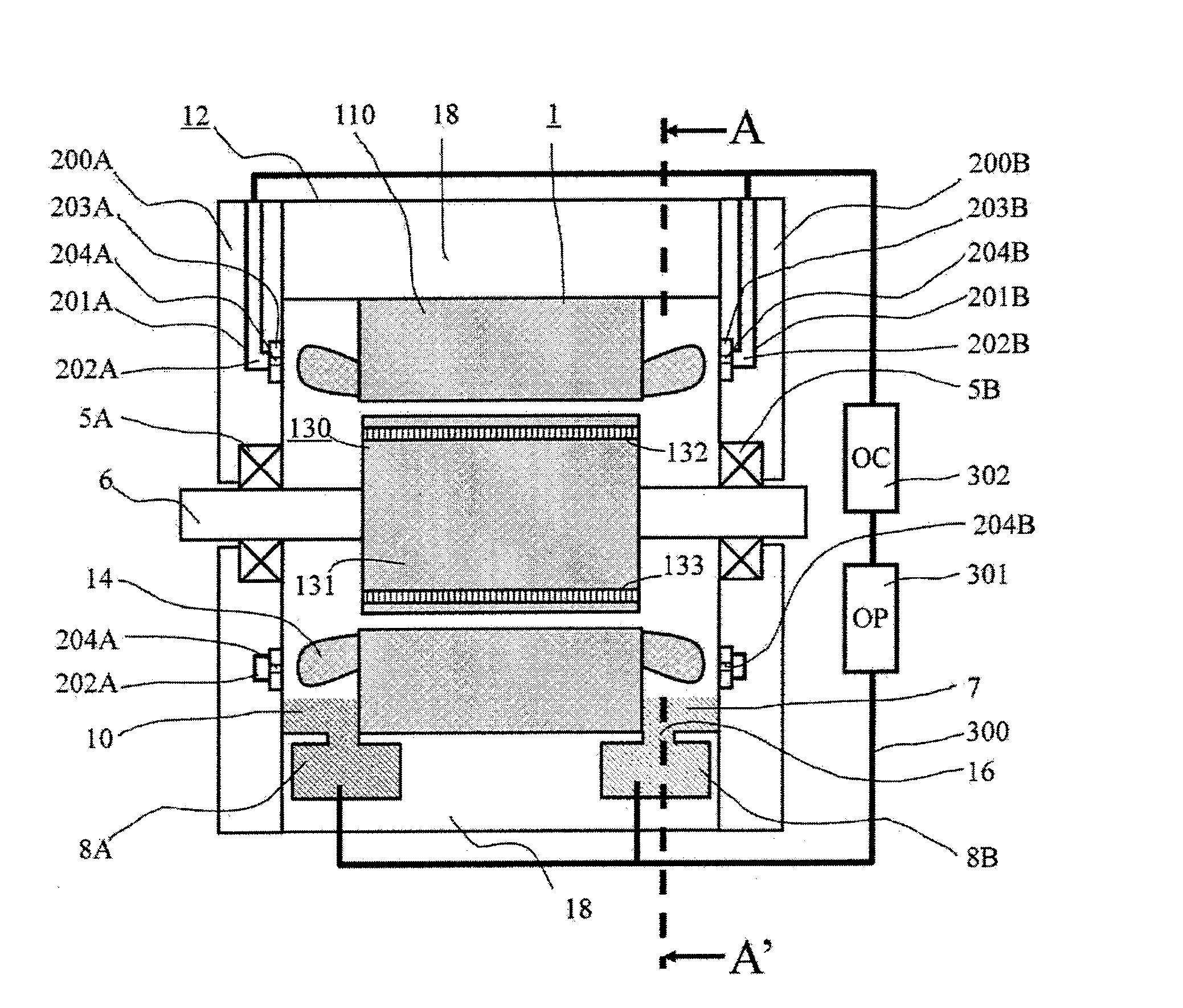
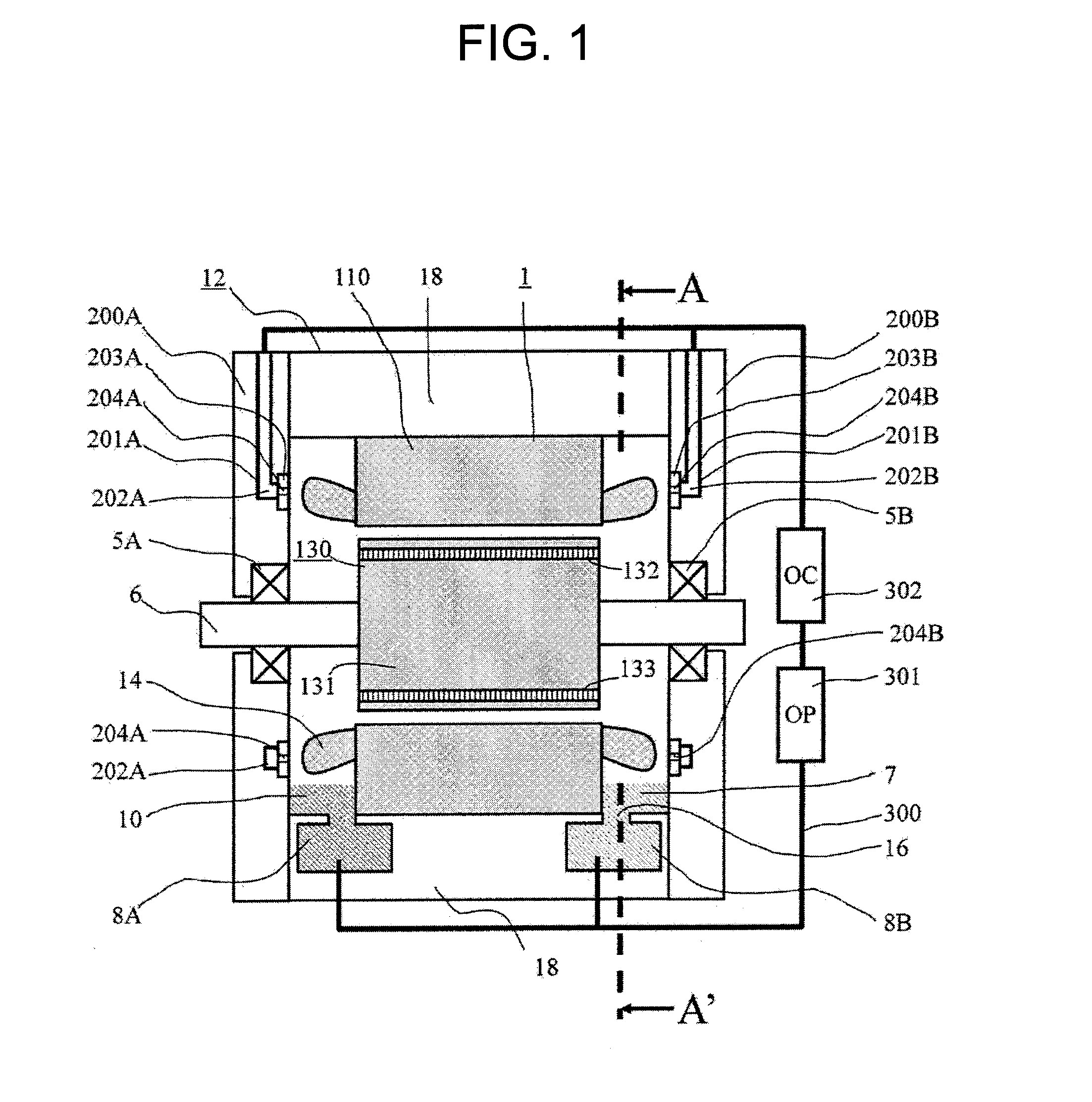
[0031]A generator motor according to a first example of the invention will be described below in detail with reference to FIGS. 1 to 5. FIG. 1 is an axially sectional view showing an overall configuration of the generator motor according to the first example of the invention. FIG. 2 is an exploded view showing an oil passage inside a bracket in the generator motor according to the first example. FIG. 3 is a sectional view showing the relation between armature windings and the positions of oil injection holes in the generator motor according to the first example. FIG. 4 is an axially vertical sectional view, which is a sectional view taken along the line of arrows A-A′ in FIG. 1, showing a housing and an auxiliary oil reservoir portion in the generator motor according to the first example. FIG. 5 is a view showing a measurement result of the temperature distribution of the armature windings in the generator motor according to the first example.

[0032]In FIG. 1, a rotor 130 has a confi...

example 2

[0047]A generator motor according to a second example of the invention will be described below with reference to FIG. 6.

[0048]FIG. 6 is a sectional view showing the relation between armature windings and the hole diameters of oil injection holes in the generator motor according to the second example. In FIG. 6, the same constituent elements as those in FIG. 3 are referred to by the same numerals correspondingly so that duplicate description thereof will be avoided.

[0049]The second example is different from the first example shown in FIG. 3 in the point that the oil injection holes 204 provided in the ring 203 are disposed in the whole circumference so that the hole diameters of the oil injection holes 204 are large in the vertically upper portion, small in the horizontal direction and small in the vertically lower portion. In other words, the second example is an example in which, of the hole diameters of the injection holes 204 provided in the bracket 200, one in the vertically upp...

example 3

[0051]A generator motor according to a third example of the invention will be described below with reference to FIG. 7. FIG. 7 is a sectional view showing the relation between armature windings and the number and the hole diameters of oil injection holes in the generator motor according to the third example. In FIG. 7, the same constituent elements as those in FIG. 3 are referred to by the same numerals correspondingly so that duplicate description thereof will be avoided.

[0052]The third example is different from the first example shown in FIG. 3 in the point that the oil injection holes 204 are provided so that the number of the oil injection holes 204 provided in the ring 203 is large in the vertically upper portion and reduced in the horizontal direction and the hole diameters of the oil injection holes 204 are large in the vertically upper portion and small in the horizontal direction.

[0053]Incidentally, although FIG. 7 depicts the example in which the hole diameters of the inje...


PUM


Abstract

To uniformly cool down armature windings along the circumferential direction of a stator in a generator motor. A generator motor includes a stator 1 fixed to the inner diameter side of a housing 18, a rotor 130 rotatably supported by bearings 5, and armature windings wound around the teeth of a stator core 110. Each of brackets 200 provided via the bearings 5 has a passage 201, 202 through which cooling oil flows and injection holes 204 which communicate with the passage and inject cooling oil at positions opposite to winding ends of the armature windings. Cooling oil is injected toward the winding ends of the armature windings from the injection holes 204 of the brackets 200 arranged on opposite axial sides of a shaft 6. In the flow rate distribution of the oil from the plurality of the injection holes 204, the flow rate of the oil from any of the injection holes 204 is set to be greater as the position of the injection hole 204 is higher above the level of the shaft 6. The arrangement pitch among the injection holes 204 provided on each of the brackets 200 is dense in a vertically upper portion of the bracket 200, and gradually sparser in a portion thereof closer to the level of shaft 6.

Description

TECHNICAL FIELD[0001]The present invention relates to a generator motor in which field permanent magnets are provided in a rotor. Particularly, it relates to a permanent magnet type generator motor for an electric vehicle, which motor is driven under a high temperature environment.BACKGROUND ART[0002]Permanent magnet type rotary electric machines have been improved in terms of performance rapidly with the development of high residual magnetic flux density magnets. For this reason, the permanent magnet type rotary electric machines have been used in all phases. Particularly, high energy efficiency has been requested for electric motors for industrial use or for household use in view of recent environmental regulations. Thus, the application ratio of the permanent magnet type electric motors tends to be extremely high.[0003]In addition, since a highly efficient system configuration can be attained as an auxiliary motive power source for an engine or a transmission in an electric motor...

Claims


Application Information

Patent Timeline
Patent Type & Authority Applications(United States)
IPC IPC(8): H02K9/19
CPCH02K9/19H02K5/161H02K3/24B60L2200/00Y02T90/16Y02T10/64H02K9/00H02K9/193H02K9/20H02K5/203B60L2200/40B60K2001/006
Inventor KIKUCHI, SATOSHIISHIDA, SEIJIMIYOSHI, TSUTOMUSAWADA, ITSUROISHIJIMA, MAKOTOAOKI, SHIGENORI
Owner NIHON KENKI CO LTD
Why Eureka
Try Eureka