Metal Object or Feature Detection Apparatus and Method

a detection apparatus and metal detector technology, applied in the field of metal detectors and methods, can solve the problems of reducing the sensitivity of the metal detector, coils becoming unbalanced, and not allowing the user to determine whether the sensed item is worth recovering, so as to improve the indication of the target's location and enhance the view of the target imag

Active Publication Date: 2014-08-07
FRY TERRY
View PDF3 Cites 35 Cited by
  • Summary
  • Abstract
  • Description
  • Claims
  • Application Information

AI Technical Summary

Benefits of technology

[0027]In both embodiments of the present invention, the metal detector is provided with a compact solid state display unit such as a commercially available GPS receiver having a touch screen display, and a plurality of user-adjustable controls. In the first embodiment, the display screen shows a dot or other avatar that moves on the screen as the detector head moves to display the relative location of a target object with respect to the head. In the second embodiment, the display screen provides a color image having blocks representative of each small sensor coil and sectors representing each of the quadrant coils, with the color of each varying with the intensity of the magnetic field detected by the sensor corresponding to that block or sector. The colors of the blocks and of the sector in the displayed image change as the detector head moves with respect to a target, indicating which sensor coil in the array is receiving the strongest signal and thus providing an accurate display of the target location.
[0042]In another embodiment, the user might wear stereo headphones with left and right ear speakers, with the audio tones generated for perception by the user being modulated in such a way that proximity of the target object is indicated by a change in intensity or loudness of the playback tone in the left or right ear speakers. In addition, a tonal change or frequency shift in the tone can be used to indicate whether the object is ferrous or non-ferrous. For example, a low frequency tone can be used to indicate detection of a ferrous object while a high frequency tone can be used to indicate detection of a nonferrous object. Directional information is also being provided to the user in this embodiment. With left and right earphones, the user can experience stereo or binaural playback so that as the pickup is swept left to right and a target object is detected, the detection tone can initially appear only in the left headphone and as the pickup is swept past the target object the apparent location of the tone can be centered between the left and right speakers, transitioning over to the right speaker as the object passes beneath the right side pixel coils, whereupon, ultimately, the tone is played back only in the right ear. In this way the user can elect either to look at the display to see the passing target avatar or can listen to the playback tone to track the relative position of the target object beneath the pickup array. Alternatively, the user can rely on both visual and audible indications of relative positions of the target object while engaging in the left to right then right to left sweeping motion while walking with the metal detector.

Problems solved by technology

One challenge for users of metal detectors is that an object may be sensed at or just below the surface of the ground, but the information about the sensed object or target item may not allow the metal detector user to determine whether the sensed item is worth recovering.
When metal, or other electrically conductive material, is introduced into their vicinity the coils become unbalanced.
Even with discriminators, however, it is still a challenge to avoid undesirable metals because some of them, such as tin foil and gold, have similar phase responses.
Discriminators may also reduce the sensitivity of the metal detector.
Another development was the invention of detectors designed to cancel out the effect of mineralization in the ground, thereby giving greater detection depth, but this feature provided poor discrimination of the sensed items or targets.
None of the metal detectors in the prior art provide a satisfactory solution to the problems frustrating metal detector users.
In addition to unreliable discrimination between valuable and worthless items, all of the prior metal detectors are frustrated by “false positive” indications in wet conductive dirt or clay for users attempting to locate dangerous metal objects such as nails or valuable objects that may be on or near the surface of the soil.
When the soil was broken down into smaller and smaller clumps, the applicant was frustrated to learn that there was no nail or other ferrous object and the false positive indication was simply the result of moisture in the soil.
Another problem found in the prior art is a lack of continuity in the detection signal when the detector is not moving; the audio signal indicating a target is only present when the detector is in motion, and fades away when the detector is stopped over or near a target.
This makes it difficult to locate a target object with precision.

Method used


Image

  • Metal Object or Feature Detection Apparatus and Method
  • Metal Object or Feature Detection Apparatus and Method
  • Metal Object or Feature Detection Apparatus and Method

Examples


first embodiment

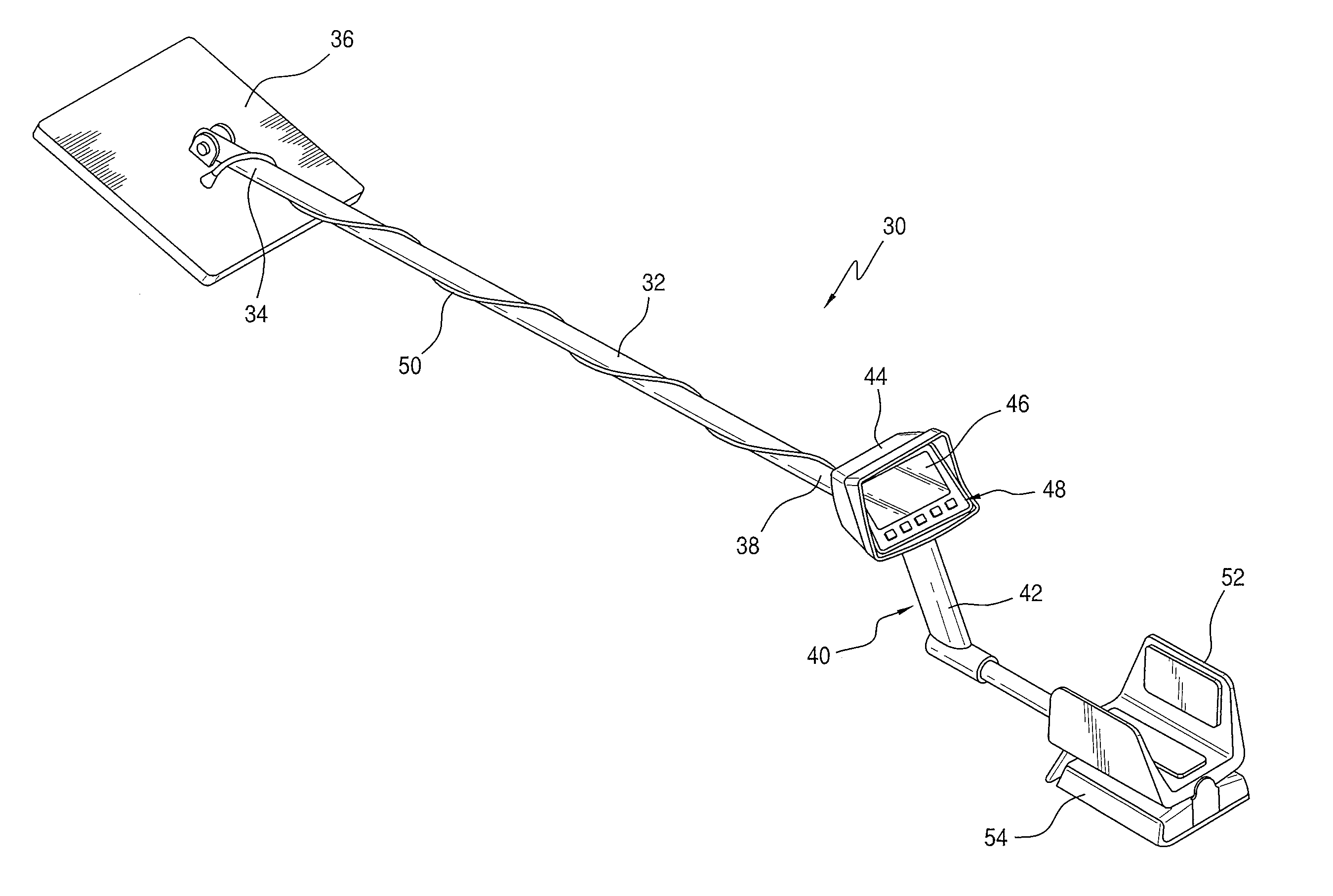
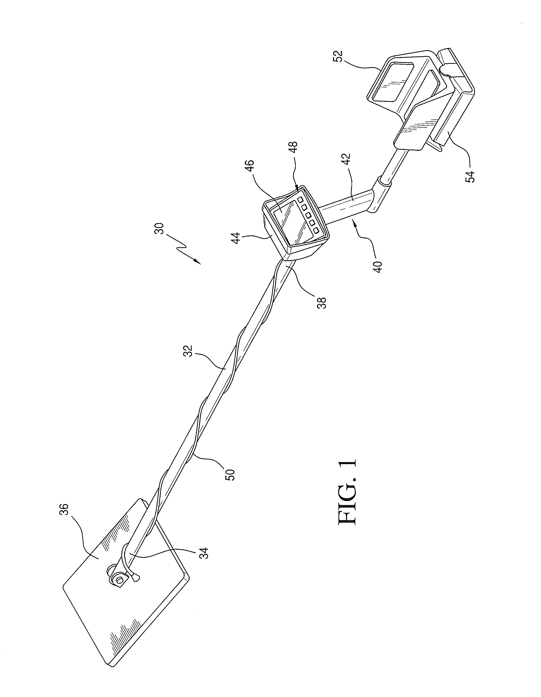
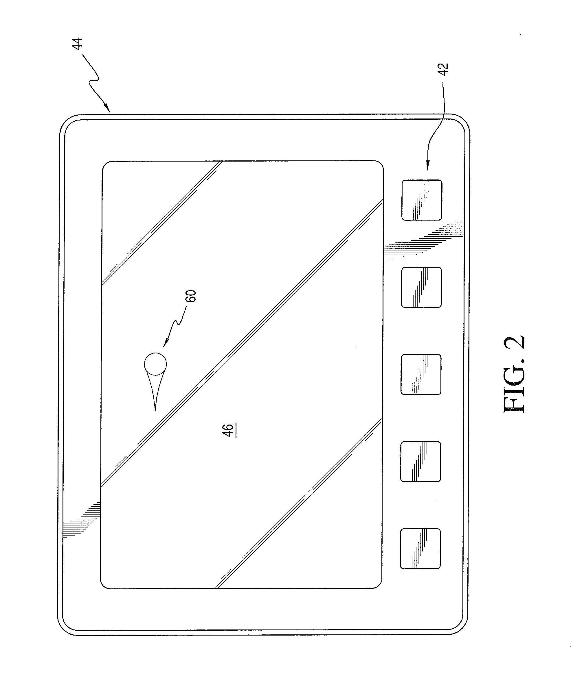
[0057]Turning now to a more detailed description of the present invention, with reference to FIGS. 1-6, there is illustrated in FIG. 1 a hand-held metal object or target detection apparatus 30 having a stem section, or shaft 32 supporting at a distal end 34 a pickup head 36 carrying a sensor array to be described, and having at a proximal or near end 38 a handle 40 having a hand grip 42. Mounted on the proximal hand grip and connected the sensor array is a controller and interface module 44 which incorporates electronic detection circuitry having signal generation and signal receiver circuits, further described below, together with a display screen 46 and an operator touch pad 48.

[0058]The pick-up or search head 36 includes transmit and receive coils that are connected via a cable 50 to the electronics package housing 38. Although illustrated as being wrapped around the stem 32, it will be understood that the cable can extend through the stem. As illustrated in FIG. 1, the detector ...

second embodiment

[0087]After adjustment and normalization of the detector 30, the user sweeps or moves the pickup array in head 36 over the soil as the perimeter coil, and the quadrant coils in the second embodiment, are illuminated. The target location information is sensed as phase changes in the induced magnetic field that is received in each of the sensor coils, and these phase changes are observable as changes in the pixel display blocks visible on display screen 46 as the user sweeps the pickup array in head 36 past a concealed target so that, in terms of relative motion, the target image traverses the display screen while the user sweeps the pickup array over ground.

[0088]In the absence of target items or objects, the display screen of detector 30 will generate an easily distinguishable 2-D image for a sensed response from uniform and homogenous soil. In the second embodiment described above, the screen 46 will provide a background color representing the conductivity of the soil. As the user ...


PUM


Abstract

A metal detector system 30 for sensing target (e.g., metal) objects within soil or other strata includes a pickup head 36 carrying an excitation coil configured to generate an excitation signal to energize a target object 400 and uses a 2-D (e.g., planar, rectangular) array of pixel-receive coils configured within the pickup head to receive electro-magnetic energy from the energized target object. As the user moves the pickup head across the strata's surface, the pixel-receive coils sense relative motion between each pixel-receive coil and the energized target object, where motion is detectable as individually sensed changes in received signal levels among the pixel-receive coils. The metal detector system also includes a 2-D display 46 which depicts or visually represents the 2-D array of pixel-receive coils and generates a changing display of any sensed moving target object 60 in response to sensed changes in received signal levels among the pixel-receive coils.

Description

[0001]The present application claims priority to copending U.S. Provisional Patent Application No. 61 / 500,783, of Terry Fry, filed Jun. 24, 2011, and entitled “Metal Object or Feature Detection Apparatus and Method,” the disclosure of which is hereby incorporated herein in its entirety, by reference.BACKGROUND OF THE INVENTION [0002]1. Field of the Invention[0003]The present invention relates to metal detectors and methods for sensing and indicating the proximity of selected target objects or features concealed within or beneath surfaces such as soil or other strata.[0004]2. Discussion of the Prior Art[0005]Metal detectors have been used by civilians and military personnel for a variety of reasons. Commonly, the civilian use of metal detectors includes the enjoyment of a hobby that, in many cases, is intended to pay for itself, meaning that individuals often purchase metal detectors for assistance in finding and recovering lost articles such as coins, jewelry and other ferrous or no...

Claims


Application Information

Patent Timeline
Patent Type & Authority Applications(United States)
IPC IPC(8): G01V3/10G01V3/165
CPCG01V3/165G01V3/104
Inventor FRY, TERRY
Owner FRY TERRY
Why Eureka
Try Eureka