Systems and methods for regulating power conversion systems with output detection and synchronized rectifying mechanisms

a technology of output detection and synchronization rectifying mechanism, which is applied in the direction of pulse technique, process and machine control, instruments, etc., can solve the problems of reducing the efficiency of the power conversion system, and significant power loss in operation

Active Publication Date: 2014-08-07
ON BRIGHT ELECTRONICS SHANGHAI
View PDF6 Cites 62 Cited by
  • Summary
  • Abstract
  • Description
  • Claims
  • Application Information

AI Technical Summary

Benefits of technology

[0026]In another embodiment, a method for regulating a power conversion system includes: receiving an input signal associated with an output voltage related to a secondary winding of a power conversion system; processing information associated with the input signal; generating a first drive signal based on at least information associated with the input signal to turn on or off a transistor to affect a first current associated with the secondary winding of the power conversion system; receiving a feedback signal associated with the first drive signal; processing information associated with the feedback signal; generating a second drive signal based on at least information associated with the feedback signal; and outputting the second drive signal to a switch to affect a second current flowing through a primary winding of the power conversion system. The generating a first drive signal based on at least information associated with the input signal includes, in response to the input signal indicating that the output voltage changing from a first value larger than a first threshold to a second value smaller than the first threshold, generating one or more pulses of the first drive signal to turn on and off the transistor. The processing information associated with the feedback signal includes: processing the feedback signal; detecting the one or more pulses of the first drive signal based on at least information associated with the feedback signal; and outputting a detection signal based on at least information associated with the detected one or more pulses. The generating a second drive signal based on at least information associated with the feedback signal includes: receiving the detection signal; outputting a modulation signal based on at least information associated with the detection signal; receiving the modulation signal; and generating the second drive signal based on at least information associated with the modulation signal. The generating a second drive signal based on at least information associated with the feedback signal further includes, in response to the one or more pulses of the first drive signal being detected, increasing a switching frequency associated with the second drive signal.

Problems solved by technology

Though the fly-back power conversion system 100 can be used for output voltage regulation, the power conversion system 100 often cannot achieve good output current control without additional circuitry of high cost.
Moreover, the required output current sensing resistor in the secondary side usually reduces the efficiency of the power conversion system 100.
Such a forward voltage often results in significant power loss in operation, and thus causes low efficiency of the power conversion system.
Therefore, the dynamic performance of the power conversion system 200 is often unsatisfactory at a low switching frequency under no / light load conditions.
If the output load changes from no / light load conditions (e.g., 0 A) to full load conditions (e.g., 1 A), the output voltage 250 drops 1 V (e.g., from 5 V to 4 V), which is often unacceptable in certain applications.

Method used


Image

  • Systems and methods for regulating power conversion systems with output detection and synchronized rectifying mechanisms
  • Systems and methods for regulating power conversion systems with output detection and synchronized rectifying mechanisms
  • Systems and methods for regulating power conversion systems with output detection and synchronized rectifying mechanisms

Examples


Embodiment Construction

[0040]The present invention is directed to integrated circuits. More particularly, the invention provides systems and methods with output detection and synchronized rectifying mechanisms. Merely by way of example, the invention has been applied to a power conversion system. But it would be recognized that the invention has a much broader range of applicability.

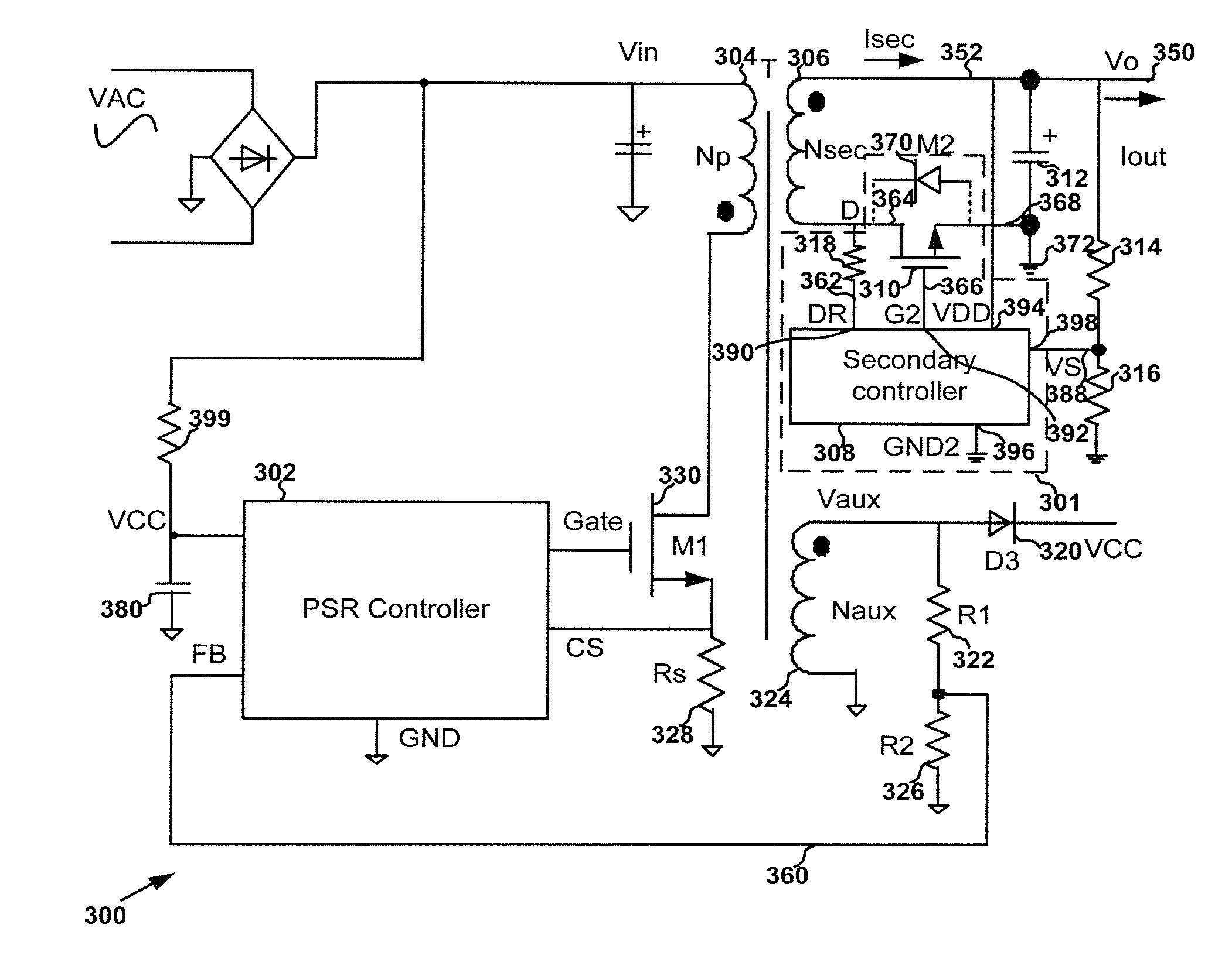
[0041]FIG. 3(A) is a simplified diagram showing a power conversion system with a rectifying circuit according to an embodiment of the present invention. This diagram is merely an example, which should not unduly limit the scope of the claims. One of ordinary skill in the art would recognize many variations, alternatives, and modifications. The power conversion system 300 includes a controller 302, a primary winding 304, a secondary winding 306, an auxiliary winding 324, a rectifying circuit 301, a diode 320, a current sensing resistor 328, capacitors 312 and 380, resistors 314, 316, 322 and 326, and a power switch 330. The rec...


PUM


Abstract

System and method for regulating a power conversion system. An example system controller includes: a first controller terminal and a second controller terminal. The system controller is configured to: receive an input signal at the first controller terminal and generate a first drive signal at the second controller terminal based on at least information associated with the input signal to turn on or off a transistor to affect a current associated with a secondary winding of the power conversion system. The system controller is further configured to: in response to the input signal changing from a first value larger than a first threshold to a second value smaller than the first threshold, change the first drive signal from a first logic level to a second logic level to turn on the transistor.

Description

1. CROSS-REFERENCES TO RELATED APPLICATIONS[0001]This application claims priority to Chinese Patent Application No. 201410093010.4, filed Mar. 13, 2014, incorporated by reference herein for all purposes. In addition, this application is a continuation-in-part of U.S. patent application Ser. No. 13 / 466,808, filed May 8, 2012, claiming priority to Chinese Patent Application No. 201210118202.7, filed Apr. 12, 2012, both of these applications commonly assigned and incorporated by reference herein for all purposes.2. BACKGROUND OF THE INVENTION[0002]The present invention is directed to integrated circuits. More particularly, the invention provides systems and methods with output detection and synchronized rectifying mechanisms. Merely by way of example, the invention has been applied to a power conversion system. But it would be recognized that the invention has a much broader range of applicability.[0003]FIG. 1 is a simplified diagram showing a conventional flyback power conversion syst...

Claims


Application Information

Patent Timeline
Patent Type & Authority Applications(United States)
IPC IPC(8): H02M3/335H02M1/00
CPCH02M3/33507H03K2017/307H02M1/0032Y02B70/10H02M1/08H02M1/0054
Inventor LUO, QIANGCAO, YAMINGFANG, LIEYI
Owner ON BRIGHT ELECTRONICS SHANGHAI
Why Eureka
Try Eureka