Method of displaying electromagnetic field in hydrogen atom

a hydrogen atom and electromagnetic field technology, applied in educational appliances, instruments, educational models, etc., can solve the problems of inappropriate magnetic field, infinite divergence at r=0,

Inactive Publication Date: 2014-08-07
MATSUSHIMA HARUO
View PDF3 Cites 7 Cited by
  • Summary
  • Abstract
  • Description
  • Claims
  • Application Information

AI Technical Summary

Benefits of technology

[0010]Since the method of displaying an electromagnetic field in a hydrogen atom according to the embodiment of the present invention adopts as a wave function of a p orbital a wave function that has its maximum value at the origin, electric fields obtained by a gradient vector operation applied to a wave function and a sign inversion applied thereafter and corresponding electric lines of force 1 all extend outwardly from the origin. Further, since electric lines of force 1 almost proportional in number to the value of a wave function are displayed, an equivalent dispersive distribution of a negative electric charge held by an electron (to be described in detail later) will easily be un...

Problems solved by technology

Further, the magnetic field, which infinitely diverges at r=0, i...

Method used


Image

  • Method of displaying electromagnetic field in hydrogen atom
  • Method of displaying electromagnetic field in hydrogen atom
  • Method of displaying electromagnetic field in hydrogen atom

Examples


example 1

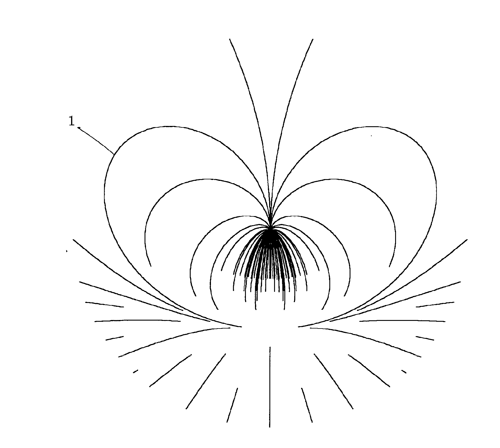
[0031]FIG. 1 is a vertical cross-sectional view showing distribution of electric lines of force 1 of a 2pz orbital in a range of a radius 6a0 obtained by use of electromagnetic field display method for a hydrogen atom as an educational tool according to the first embodiment of the present invention. A following formula is obtained by applying a gradient vector operation and a sign inversion to the wave function Ψ2pz of a 2pz orbital shown in Formula 4.

E=-grad{u200(r,θ,φ)+u210(r,θ,φ)}={(2-cosθ-r / 2a0+rcosθ / 2a0)ir+sinθiθ}exp(-r / 2a0) / 2a0(9)

[0032]Electric lines of force 1 are drawn by applying a method similar to that disclosed in Patent Document 2 to the result shown in Formula 9. The number of the electric lines of force 1 is made proportional to the percentage of a difference between the maximum and minimum values of the wave function Ψ2pz given by Formula 4, and around 100 lines in total. Since FIG. 1 shows a complicated pattern, and the method of making the electric lines of force 1...

example 21

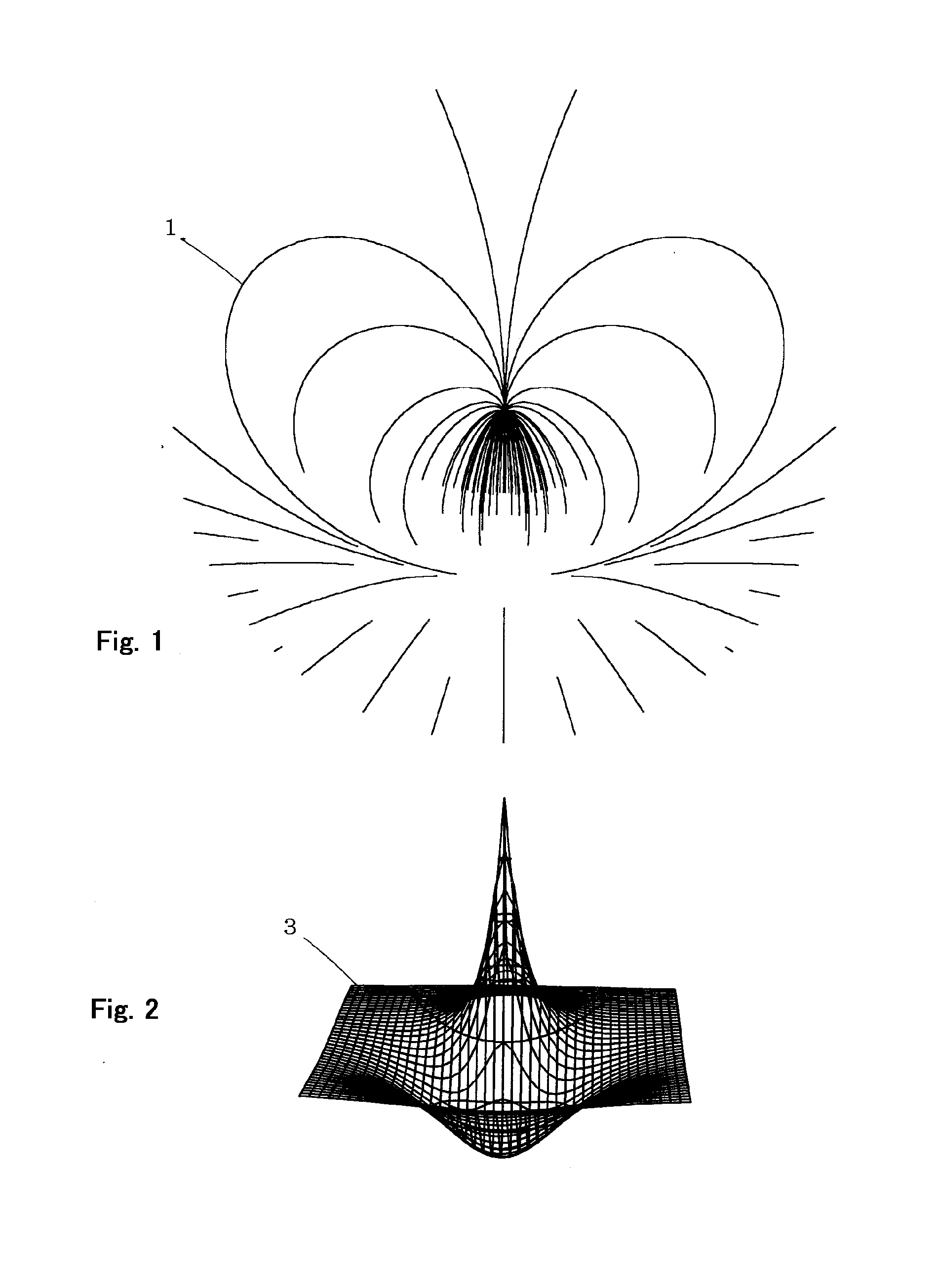
[0033]FIG. 2 is a contour drawing showing an electric potential 3 of a 2pz orbital obtained by use of an electromagnetic field display method for a hydrogen atom as an educational tool according to the third embodiment of the present invention. Spreadsheet software Excel provided by Microsoft (trademark) was used. Formula 4 representing a wave function of a 2pz orbital was substituted with r=(z2+x2)1 / 2 and r cos θ=z. A row of the matrix of the spreadsheet were filled with z and a column with x in a range from −10a0 to +10a0. Each cell as an intersection was filled with (1−r / 2−r cos θ / 2)exp(−r / 2). A contour diagram was drawn for the whole area, and scale marks, references and the like were deleted. The diagram, although being drawn under the condition that y=0 for convenience, shows an electric potential 3 on a vertical cross-section at any of φ. FIG. 2 is placed under FIG. 1 with its center accorded with that of FIG. 1 in horizontal position.

example 31

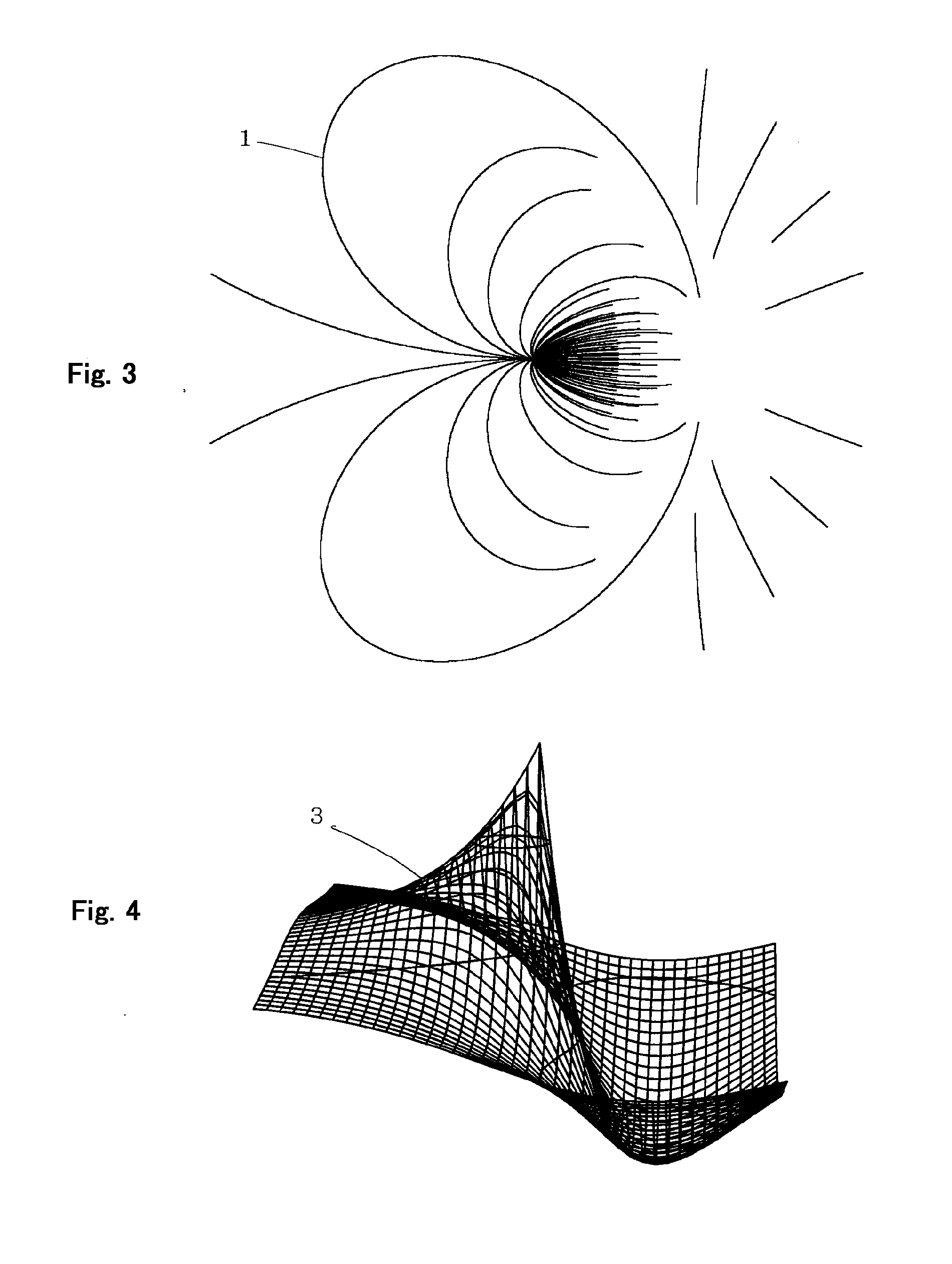
[0034]FIG. 3 is a vertical cross-sectional view showing the distribution of electric lines of force 1 of a 2px orbital obtained by an electromagnetic field display method for a hydrogen atom as an educational tool according to the first embodiment of the present invention. FIG. 3 is drawn in the same range of a radius 6a0 and in the same scale as FIG. 1. A gradient vector operation and a sign inversion were applied to the wave function Ψ2px of a 2px orbital given by Formula 7. An electric field on a vertical cross-section where φ=0 and φ=π is given as follows.

E=-grad{u200(r,θ,φ)+u211(r,θ,φ)}={(2-r / 2a0+sinθ-rsinθ / 2a0)ir+cosθiθ}exp(-r / 2a0)(10)

[0035]In the same manner as FIG. 1, the electric lines of force 1 almost proportional in number to the percentage of a difference between the maximum and minimum values of the wave function Ψ2px of a 2px orbital are drawn.


PUM


Abstract

The method assumes that a single solution or addition or subtraction of solutions of Schrodinger equation represented by polar or parabolic coordinates having its maximum value at the origin gives a wave function and an electric potential of a hydrogen atom. The method further: (1) regards the result of applying a gradient vector operation and thereafter a sign inversion to the wave function as an electric field; regards segments connected successively along the direction of the electric field as electric lines of force; and draws the electric lines of force so as to be approximately proportional in number to the percentage of the wave function with a difference between the maximum and minimum values of the wave function regarded as 100; and (2) displaying the wave function as an electric potential in a contour drawing.

Description

CROSS-REFERENCE STATEMENT[0001]This application is based on Japanese patent application serial No. 2013-32558, filed with Japan Patent Office on Feb. 4, 2013. The content of the application is hereby incorporated by reference.BACKGROUND OF THE INVENTION[0002]1. Field of the Invention[0003]The present invention relates to an improvement in displaying an electromagnetic field in a hydrogen atom as a scientific educational tool.[0004]2. Description of Related Art[0005]There are known US2010 / 0028840A1 (hereinafter referred to as Patent Document 1) and US2012 / 0202182A1 (hereinafter referred to as Patent Document 2) as documents disclosing conventional methods of displaying an internal electromagnetic field as a structure of a hydrogen atom.[0006]FIG. 1 of Patent Document 2, which is shown in FIG. 11 herein, shows electric lines of force 1 as an electric field on a vertical plane of a 2pz orbital. The electric lines of force 1, however, extend upward from the coordinate origin placed at t...

Claims


Application Information

Patent Timeline
IPC IPC(8): G09B23/26
CPCG09B23/26G09B23/20
Inventor MATSUSHIMA, HARUO
Owner MATSUSHIMA HARUO
Why Eureka
Try Eureka