Endoscope with Pannable Camera

a technology of endoscope and pannable camera, which is applied in the field of endoscopic instruments, can solve the problems of long recovery time, complicated anesthesia associated with open surgery, and comparatively more time-consuming to repair these anatomical areas

Active Publication Date: 2014-08-07
DEKA PROD LLP
View PDF4 Cites 104 Cited by
  • Summary
  • Abstract
  • Description
  • Claims
  • Application Information

AI Technical Summary

Benefits of technology

[0010]The insertion section of an endoscope may also comprise a conduit, the conduit being configured to transfer fluid (liquid and/or gas) between a space in which the tip of the insertion section is positioned and a location external to the endoscope. The conduit may also be configured to carry functional components of the endoscope, including (but not limited to) a camera, camera mount, fiberoptic cable, electronic transmission cable, and mechanical pull wi

Problems solved by technology

Standard techniques of open surgery to view and repair these anatomical areas can be comparatively more time consuming, associated with greater risk and trauma to a patient, and can be associated with longer recovery time.
Furthermore, anesthesia associated with open surgery may be more complicated, risky and costly.
This may not be an effective option when the tip of the instrument is positioned in a confined space that may not accommodate the range of motion required for flexing the distal segment of an endoscope.
However, rig

Method used


Image

  • Endoscope with Pannable Camera
  • Endoscope with Pannable Camera
  • Endoscope with Pannable Camera

Examples


Embodiment Construction

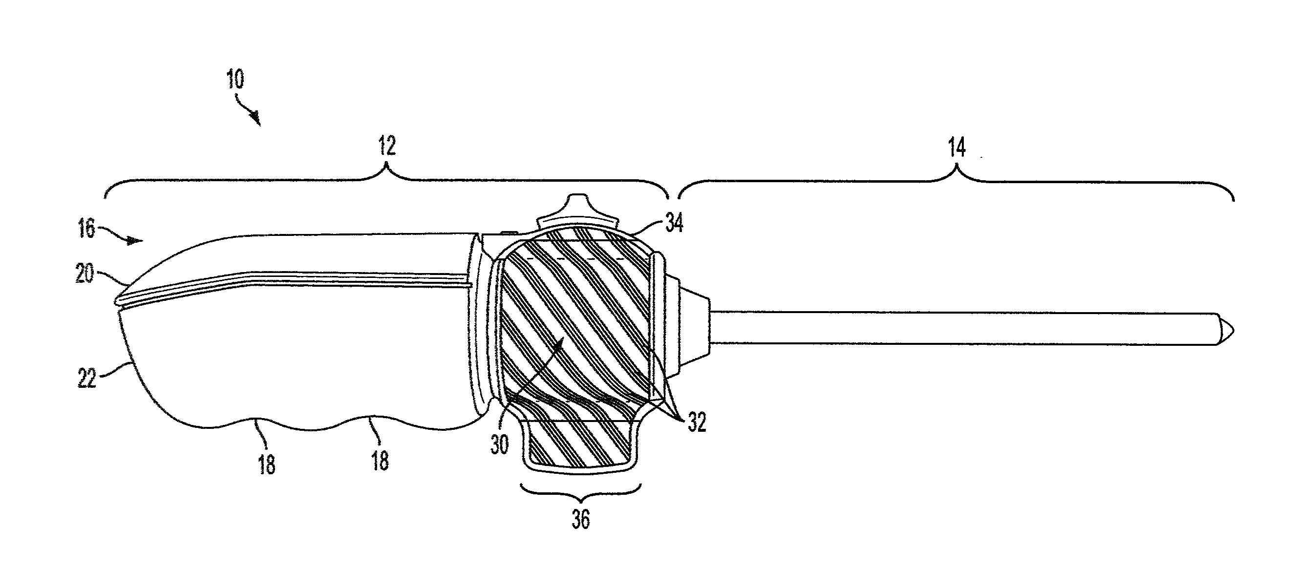
[0099]The terms ‘endoscope’ and ‘arthroscope’ as used herein are meant to be used interchangeably and are to be given their broadest interpretation, each term denoting an instrument having an elongate section for insertion into a space that is otherwise difficult to access, for the purpose of visual inspection, diagnosis and / or treatment or repair. In the field of medicine or veterinary practice, such a space may include a body cavity, joint space, tissue plane or other body structure. The instrument may also be used in a number of non-medical (e.g., industrial) applications, in which the diameter of the insertion portion of an endoscope needs to be minimized, or in which the space within which an endoscope must operate is too confined to permit the use of an actively flexible distal segment.

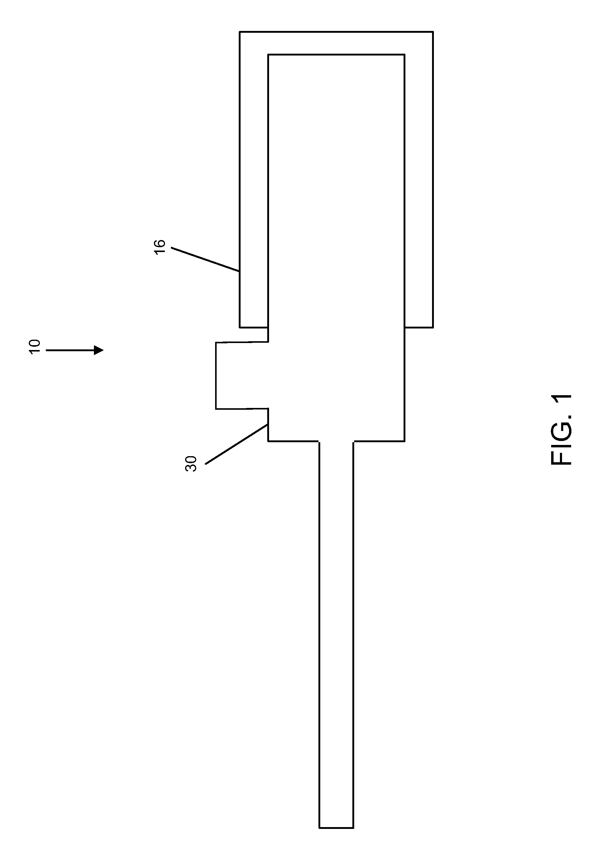
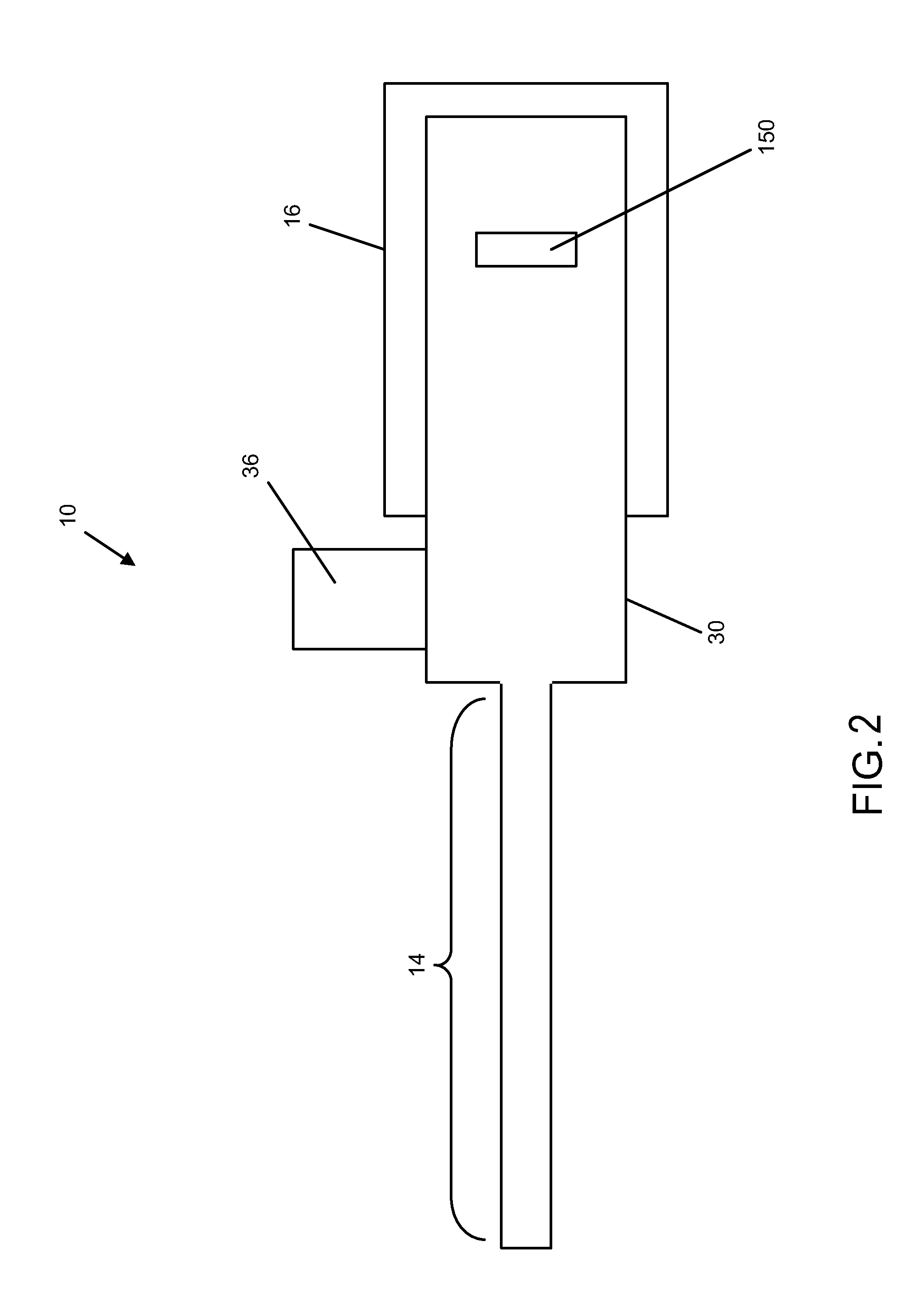
[0100]A two-component handle design of an endoscope 10 is shown in FIG. 1. The example endoscope 10 includes a handle proximal section 16 and a handle distal section 30. The handle proximal sect...


PUM


Abstract

An endoscope has a pannable camera at the distal end of its insertion shaft, the pannable camera assembly being pivotable to provide a range of a field of view that can be equal to or greater than 180 degrees. A terminal light emitting element may be mounted to the camera assembly in order to illuminate the immediate field of view of the camera sensor regardless of the rotational position of the camera assembly. A fluid-carrying conduit of the insertion section may also be used to house functional components, including the camera assembly, actuation cables, a communications cable connected to the camera sensor, and/or a fiberoptic cable providing light to the light emitting element. A distal section of the endoscope handle may be rotatable relative to a proximal hand-held section of the endoscope handle, a rotary encoder being provided to convert the rotational position of the insertion shaft relative to the handle into a signal for the purpose of image orientation correction by an electronic processor.

Description

CROSS-REFERENCES TO RELATED APPLICATIONS[0001]The present application is a Non-Provisional application which claims the benefit of U.S. Provisional Patent Application Ser. No. 61 / 826,303, filed May 22, 2013 and entitled Endoscope with Pannable Camera (Attorney Docket No. K35); and U.S. Provisional Patent Application Ser. No. 61 / 759,784, filed Feb. 1, 2013 and entitled Pannable Endoscope (Attorney Docket No. K29), each of which is hereby incorporated herein by reference in its entirety.BACKGROUND[0002]1. Field of Disclosure[0003]The present disclosure relates to endoscopic instruments for viewing and working in relatively inaccessible spaces; and in some aspects for operating in tight anatomical spaces within a body using an endoscope or arthroscope, or the like.[0004]2. Background Information[0005]The use of endoscopic instruments in medicine, allowing for remote viewing and operating in difficult-to-access spaces has become well-established. These instruments have also been useful ...

Claims


Application Information

Patent Timeline
IPC IPC(8): A61B1/00A61B1/015A61B1/045A61B1/05
CPCA61B1/00183A61B1/05A61B1/045A61B1/015A61B1/00165A61B1/00096A61B1/0011A61B1/051A61B1/126A61B2017/3456A61B2090/306A61B2090/3616A61B1/00103
Inventor GRANT, KEVIN L.DEMERS, JASON A.KANE, DEREK G.VONDRAS, PETER K.FICHERA, STEPHEN L.MOREAU, TIMOTHY D.TRACEY, BRIAN D.
Owner DEKA PROD LLP
Why Eureka
Try Eureka