Seawater infiltration method and water infiltration intake unit

a technology of water infiltration and intake unit, which is applied in the direction of water cleaning, filtration treatment, and membranes, can solve the problems of increased turbidity, high initial cost, and water intake must be stopped, so as to prevent clogging, reduce the scale of construction during installation, and facilitate maintenance. effect of system

Inactive Publication Date: 2014-08-14
HITACHI ZOSEN CORP +1
View PDF3 Cites 6 Cited by
  • Summary
  • Abstract
  • Description
  • Claims
  • Application Information

AI Technical Summary

Benefits of technology

[0024]According to the present invention, clogging can be prevented by removing living organisms or sediments accumulated in the surface layer and trapped in the intermediate layers of the sand filtration layer, and continuous high-speed filtration can be achieved, by maintaining the seawater infiltration rate as high as possible under 400 m / day. Moreover, when water infiltration intake units of the present invention are combined to form the sand filtration layer, the scale of construction during installation in greatly reduced. In addition, it becomes easy to maintain the system, because after the system starts operating, a water infiltration intake unit with a problem can be separated and replaced as a unit module.

Problems solved by technology

However, when employing the direct water intake method, debris, sediments, and living organisms are all taken in at the same time together with seawater, and thus there are cases in which water intake has to be stopped, for example, when there is abnormal adhesion of jellyfish or algal blooms, oil spill accidents, and increased turbidity due to high waves.
Although none of the problems of the direct water intake method arises when this indirect water intake method is employed, there are problems such as initial high cost and reduced water intake volume due to clogging at the infiltration surface, and consequently, this method has been slow in achieving widespread use.
However, in the seawater infiltration intake method disclosed in Patent Reference 1, a large surface area is needed for the intake of a large volume of seawater in a short period of time, because the seawater infiltration intake rate of 1-8 m / day is a very slow infiltration rate, and therefore requires a large-scale construction (Problem 1).
In addition, in the seawater infiltration intake method disclosed in Patent Reference 1, it is necessary to install the filtration intake system in the ocean area where the optimum flow of seawater is obtained, so as to prevent clogging of the sand filtration layer by silt (or sludge) which accumulates in the surface layer, thereby limiting it to sites where seawater is moved by waves (Problem 2).
However, the upper limit for the intake rate that could be realistically implemented was 400 m / day.
However, in a method which utilizes the movement of seawater, or in the case of a method which injects water and the like from a clogging prevention device installed on the surface of the sand filtration layer, it is only possible to remove sediments which accumulate in the surface layer of the sand filtration layer, and it is not possible to remove living organisms and sediments trapped in intermediate layers which are deeper than the surface layer of the sand filtration layer.
In particular, in cases where the seawater infiltration rate is set as high as possible under 400 m / day, clogging readily progresses in the intermediate layers of the sand filtration layer as well, so clogging occurs more frequently.

Method used


Image

  • Seawater infiltration method and water infiltration intake unit
  • Seawater infiltration method and water infiltration intake unit
  • Seawater infiltration method and water infiltration intake unit

Examples


examples

[0045]An embodiment of the present invention is described in detail below, using FIG. 1 to FIG. 13.

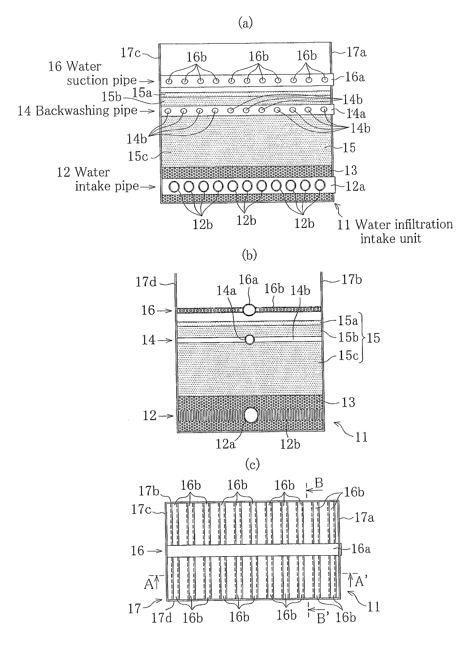
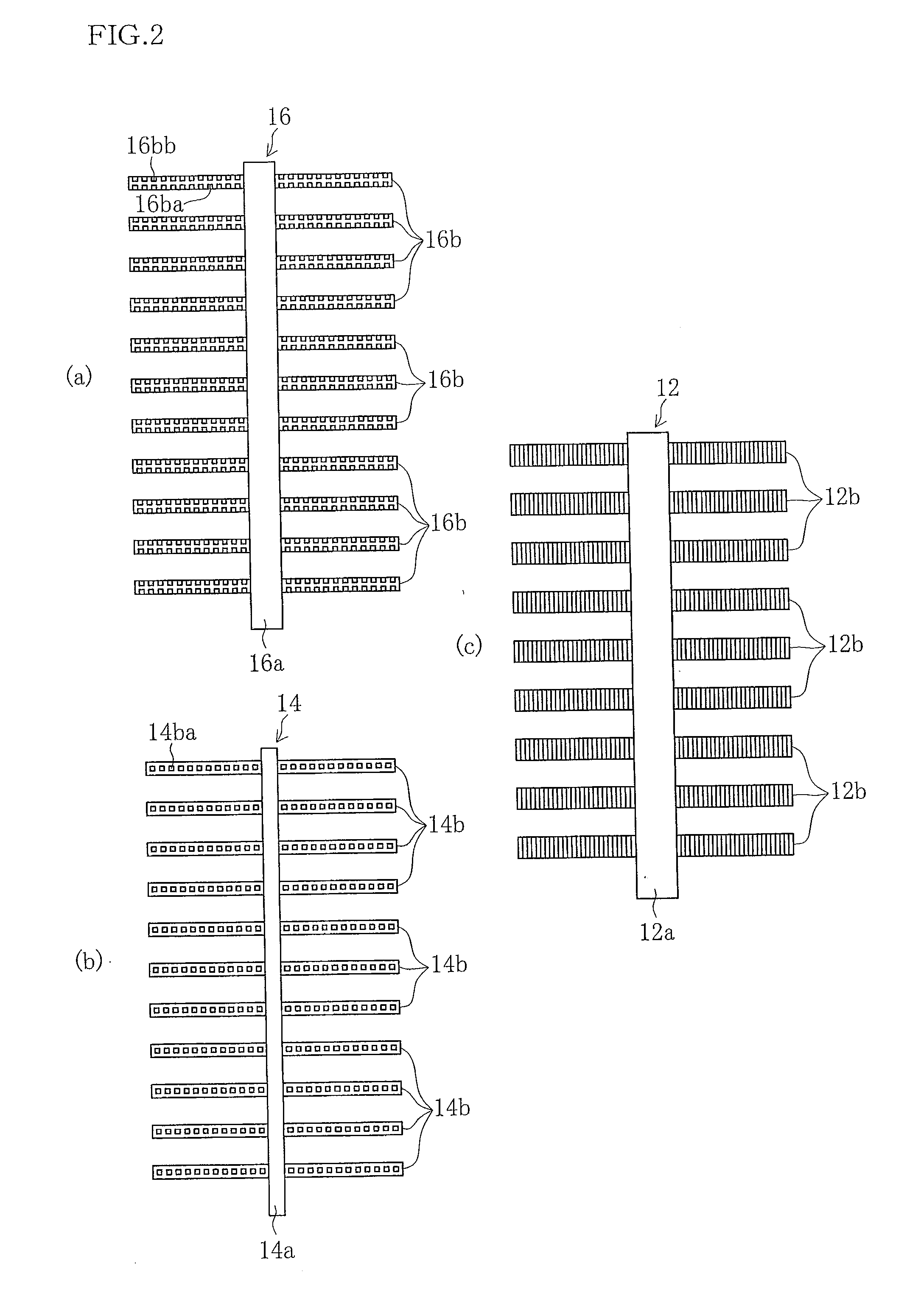
[0046]FIG. 1 is a drawing illustrating an example of a water infiltration intake unit 11 used in the seawater infiltration method of the present invention.

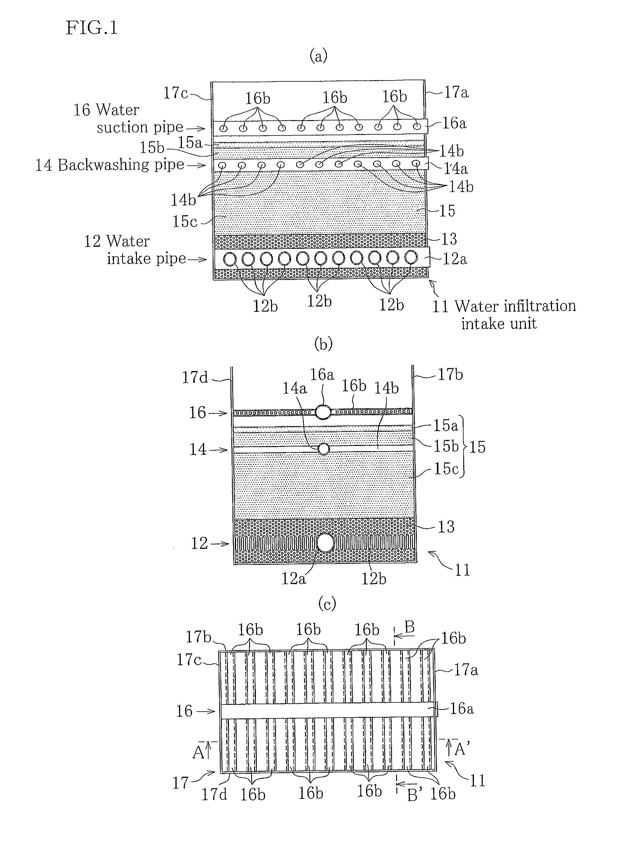
[0047]In FIG. 1(a) and FIG. 1(b), Reference Numeral 12 is a water intake pipe embedded in a gravel layer 13 which forms a deep layer of a sand filtration layer on the ocean floor. The water intake pipe 12 is formed from a main pipe 12a and a plurality of branch pipes 12b which branch in a direction crossing the main pipe 12a. Embedded in a sand layer 15 formed from intermediate layers 15b and 15c and a surface layer 15a of a sand filtration layer is a backwashing pipe 14 formed from a main pipe 14a and a plurality of branch pipes 14b which branch in a direction crossing the main pipe 14a.

[0048]In FIG. 1(c), Reference Numeral 16 is a water suction pipe formed from a main pipe 16a and a plurality of branch pipes 16b. As shown in FIG. ...


PUM


Abstract

To clean sediments and the like trapped not only in a top layer of a sand filtration layer, but also in intermediate layers. A seawater infiltration method which uses a water infiltration intake unit which is formed in advance and provided with a water intake pipe embedded in a gravel layer which forms a deep layer of the sand filtration layer, and a backwashing pipe embedded in a sand layer which forms an intermediate layer and a surface layer of the sand filtration layer, and a water suction pipe which is disposed above the sand layer. A desired number of water infiltration intake units are combined to form a sand filtration layer at an installation site on an ocean floor, and they intake seawater from the sea which has undergone natural infiltration in the sand filtration layer and this is introduced into the water intake pipe. The seawater infiltration rate is set at less than 400 m / day. Water or air is injected from the backwashing pipe to agitate and blow upward from the surface layer living organisms or sediments trapped in intermediate layers of the sand filtration layer, and the agitated water is sucked in by a suction pipe and recovered. The seawater infiltration rate can be maintained as high as possible under 400 m / day.

Description

TECHNICAL FIELD[0001]The present invention relates to a filtration method employed for intake of seawater which infiltrates through a sand layer on an ocean floor, and a water infiltration intake unit for implementing the filtration method which has a backwashing pipe or the like which prevents clogging by removing living organisms or sediments which accumulate in a surface layer of the sand layer and which become trapped in intermediate layers.BACKGROUND ART[0002]As shown in FIG. 14, as an example of a present seawater intake method, a direct water intake method is used in which seawater is taken in from a water intake orifice 1 via a water conduit 2 provided on the ocean floor. In FIG. 14, Reference Numeral 3 is a pump for taking in the seawater, and Reference Numeral 4 is a reverse osmosis membrane system.[0003]However, when employing the direct water intake method, debris, sediments, and living organisms are all taken in at the same time together with seawater, and thus there ar...

Claims


Application Information

Patent Timeline
Patent Type & Authority Applications(United States)
IPC IPC(8): E03B3/04
CPCE03B3/04B01D61/04B01D2311/04B01D2311/2649C02F1/004C02F1/441C02F2103/08Y02A20/131
Inventor NIIZATO, HIDEYUKIINOUE, TAKAYUKIARAI, HIRONARIMUKAI, KIYOKAZUMIMURA, HITOSHI
Owner HITACHI ZOSEN CORP
Why Eureka
Try Eureka