
Gas system for reactive deposition process

a technology of reactive deposition and gas system, which is applied in the direction of vacuum evaporation coating, combustion types, lighting and heating apparatus, etc., can solve the problems of similar difficulties and pluriverse difficulties of other deposition processes

Active Publication Date: 2014-08-14
APPLIED MATERIALS INC
View PDF5 Cites 8 Cited by
  • Summary
  • Abstract
  • Description
  • Claims
  • Application Information

AI Technical Summary

Benefits of technology

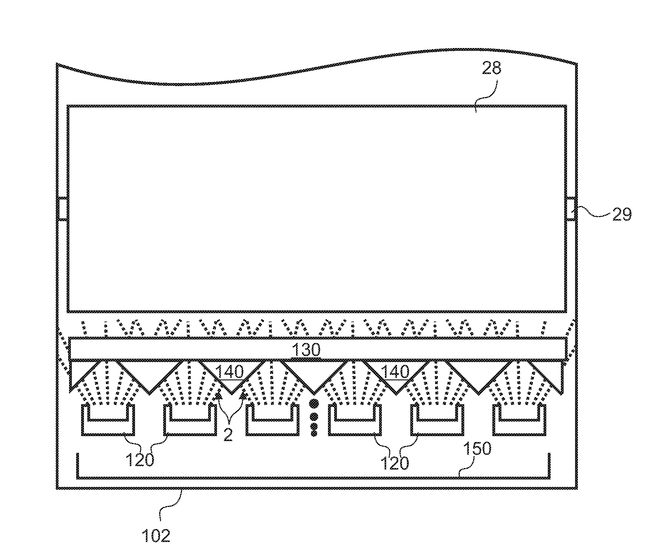
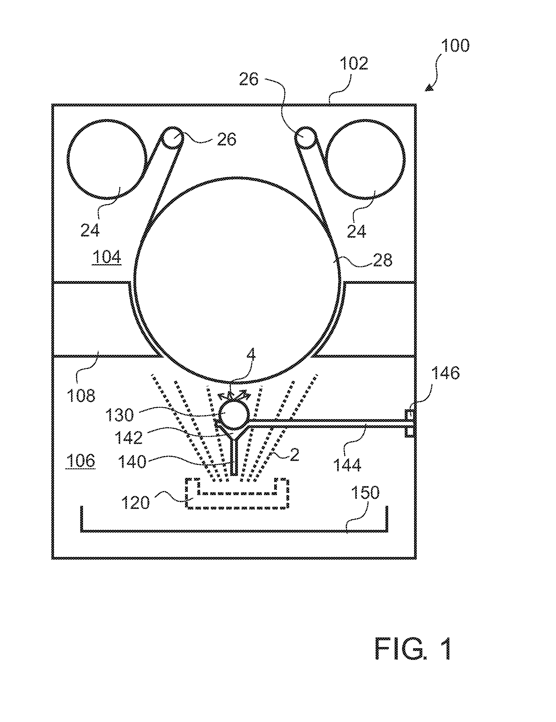
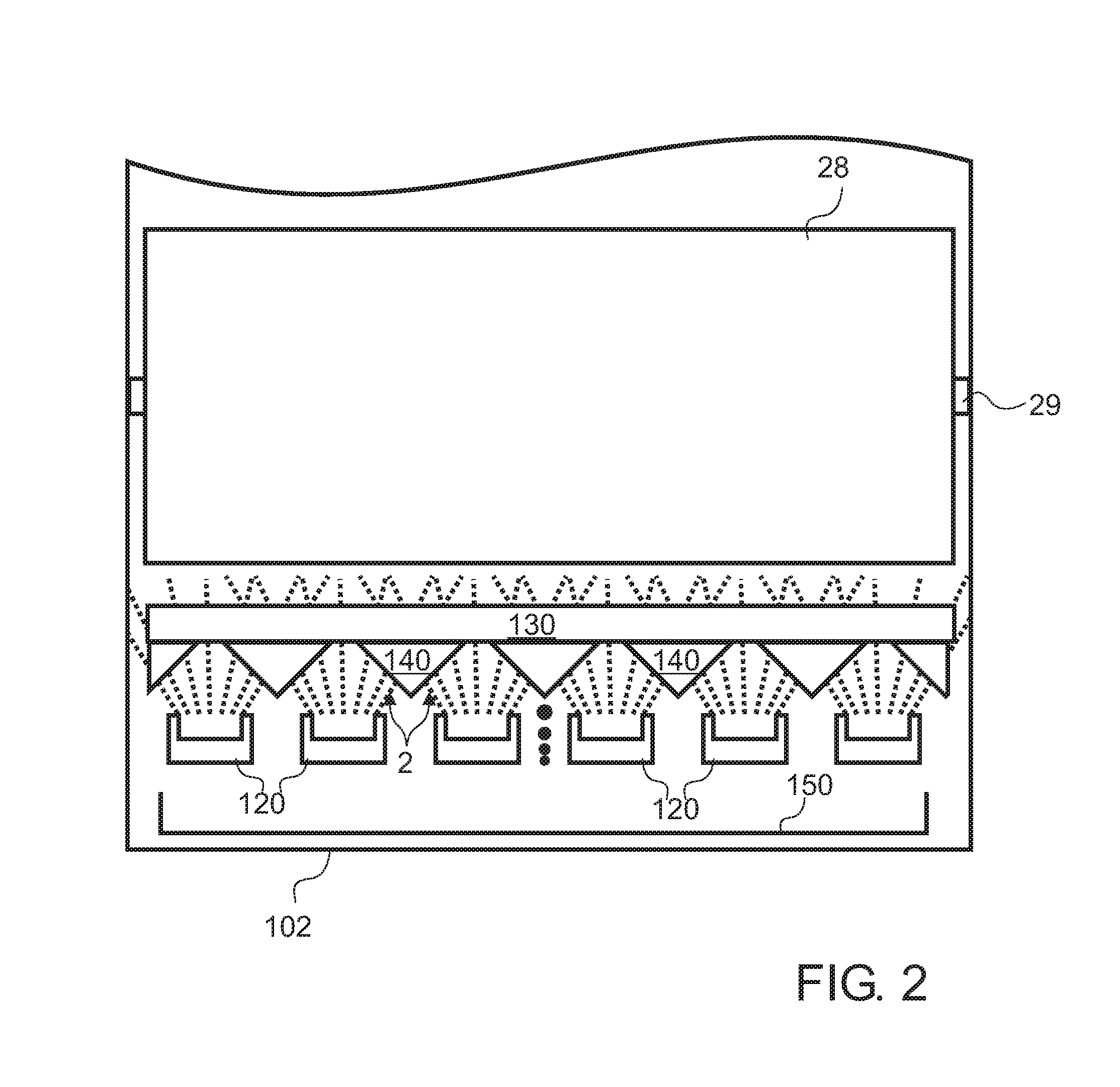
The present invention provides a gas lance unit for a reactive deposition process with a plurality of spaced apart crucibles, an evaporation apparatus with the gas lance unit, and a method for operating the evaporation apparatus. The gas lance unit provides a gas for the reactive deposition process while the condensate guiding element guides a condensate, particularly an aluminum condensate, to positions above the spaces between the crucibles. The apparatus and method allow for efficient evaporation and deposition of materials onto a substrate.

Problems solved by technology

In light of the fact that aluminum vapor is highly reactive and aggressive and in light of the fact that the reactive gas needs to be guided close to the aluminum vapor or even within the cloud of aluminum vapor, there is a plurality of difficulties.
Even though these difficulties might be particularly crucial for reactively depositing aluminum oxide, similar difficulties might occur for other deposition processes where metals or other materials are reactively deposited as oxides, nitrites or other forms.

Method used


Image

  • Gas system for reactive deposition process
  • Gas system for reactive deposition process
  • Gas system for reactive deposition process

Examples


Embodiment Construction

[0017]Reference will now be made in detail to the various embodiments of the invention, one or more examples of which are illustrated in the figures. Within the following description of the drawings, the same reference numbers refer to the same components. Generally, only the differences with respect to individual embodiments are described. Each example is provided by way of explanation of the invention and is not meant as a limitation of the invention. Further, features illustrated or described as part of one embodiment can be used on or in conjunction with other embodiments to yield yet a further embodiment. It is intended that the description includes such modifications and variations.

[0018]According to some embodiments, evaporation processes and evaporation apparatus for layer deposition on substrates, for example on flexible substrates, are provided. Thereby, flexible substrates can be considered to include inter alia films, foils, webs, strips of plastic material, metal or oth...


PUM

PropertyMeasurementUnit
Temperatureaaaaaaaaaa
Areaaaaaaaaaaa

Abstract

A gas lance unit configured for a reactive deposition process with a plurality of spaced apart crucibles, wherein spaces are provided between the crucibles, is described. The gas lance unit includes a gas guiding tube having one or more outlets for providing a gas for the reactive deposition process, and a condensate guiding element for guiding a condensate, particularly an aluminum condensate, to one or more positions above the spaces.

Description

TECHNICAL FIELD OF THE INVENTION[0001]Embodiments of the present invention relate to gas lance units for providing gas for a reactive deposition process, reactive deposition apparatuses and methods of reactive deposition. Embodiments of the present invention particularly relate to a gas lance unit configured for a reactive deposition process with a plurality of spaced apart crucibles, an evaporation apparatus for a reactive deposition process, and a method of operating an evaporation apparatus.BACKGROUND OF THE INVENTION[0002]Processing of flexible substrates, such as plastic films or foils, is in high demand in the packaging industry, semiconductor industries and other industries. Processing may consist of coating of a flexible substrate with a desired material, such as a metal, in particular aluminum. Systems performing this task generally include a processing drum, e.g., a cylindrical roller, coupled to a processing system for transporting the substrate and on which at least a po...

Claims


Application Information

Patent Timeline
IPC IPC(8): C23C14/24C23C14/00
CPCC23C14/0021C23C14/243C23C14/562C23C14/564
Inventor HOFFMANN, GERDWOLFF, ALEXANDER
Owner APPLIED MATERIALS INC
Learn More