Apparatus for coating formation by light reactive deposition

a technology of reactive deposition and apparatus, applied in the direction of liquid/solution decomposition chemical coating, optical waveguide light guide, transportation and packaging, etc., can solve the problems of inability to easily adapt to obtain more uniform coating, and inability to achieve uniform coating. , to achieve the effect of high ra

Inactive Publication Date: 2015-10-20
NANOGRAM
View PDF157 Cites 4 Cited by
  • Summary
  • Abstract
  • Description
  • Claims
  • Application Information

AI Technical Summary

Problems solved by technology

Furthermore, the individual components integrated in the devices are shrinking in size.
Flame hydrolysis deposition is efficient, but cannot be easily adapted to obtain more uniform coatings.
Chemical vapor deposition can achieve very uniform materials, but the process is extremely slow.
If attempts are made to increase the rates, the film quality is compromised, which reduces any advantage of the chemical vapor deposition process.

Method used


Image

  • Apparatus for coating formation by light reactive deposition
  • Apparatus for coating formation by light reactive deposition
  • Apparatus for coating formation by light reactive deposition

Examples


examples

[0243]This example describes the successful coating of a silicon substrate with a silicon oxide glass using light reactive deposition.

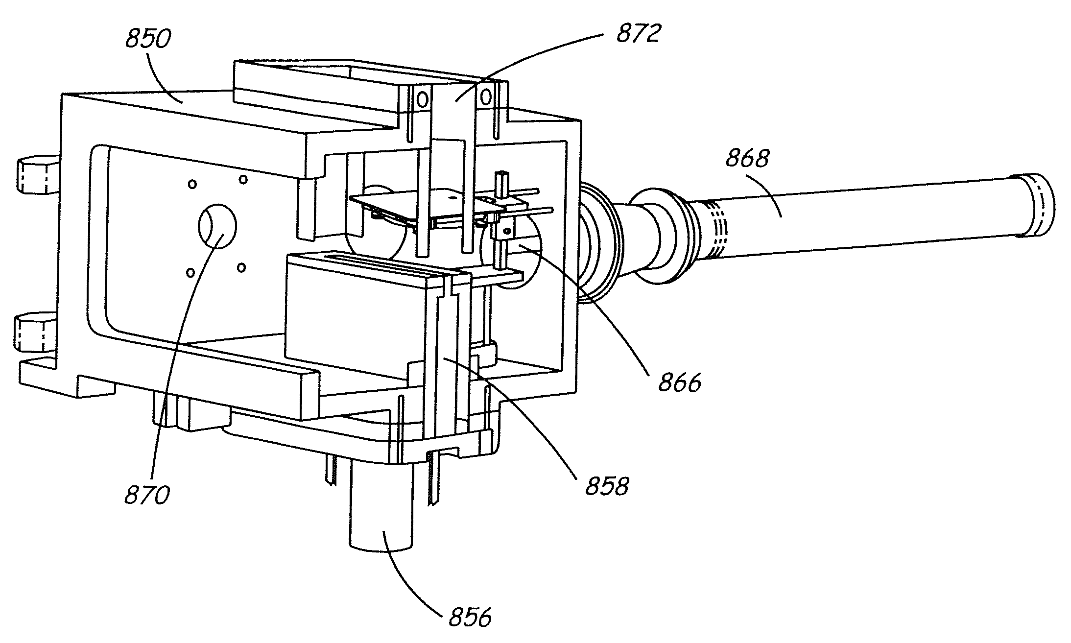
[0244]Particle coating was been performed using light reactive deposition in which wafer coating was been performed within the reaction chamber by sweeping the substrate through a product particle stream. This example focuses on this embodiment, although successful coating of a wafer within the reaction chamber has also been performed in preliminary experiments with a fixed substrate.

[0245]The apparatus used to coat a substrate / wafer moved through the reaction stream is shown in FIGS. 31-33. Referring to FIG. 31, process chamber 850 includes a light tube 852 connected to a CO2 laser and a light tube 854 connected to a beam dump. An inlet tube 856 connects with a precursor delivery system that delivers vapor reactants and carrier gases. Inlet tube 856 leads to process nozzle 858. A particle transport tube 860 connects to process chamber 850 along the f...


PUM

PropertyMeasurementUnit
pressureaaaaaaaaaa
diameteraaaaaaaaaa
diameteraaaaaaaaaa

Abstract

Light reactive deposition uses an intense light beam to form particles that are directly coated onto a substrate surface. In some embodiments, a coating apparatus comprising a noncircular reactant inlet, optical elements forming a light path, a first substrate, and a motor connected to the apparatus. The reactant inlet defines a reactant stream path. The light path intersects the reactant stream path at a reaction zone with a product stream path continuing from the reaction zone. The substrate intersects the product stream path. Also, operation of the motor moves the first substrate relative to the product stream. Various broad methods are described for using light driven chemical reactions to produce efficiently highly uniform coatings.

Description

CROSS REFERENCE TO RELATED APPLICATIONS[0001]This application is a divisional of U.S. patent application Ser. No. 10 / 414,443 now abandoned to Bi et al. filed on Apr. 15, 2003, entitled “Coating Formation By Reactive Deposition,” incorporated herein by reference, which is a continuation of International Application PCT / US01 / 32413, designating the U.S. filed on Oct. 16, 2001 to Bi et al., entitled “Coating Formation By Reactive Deposition,” incorporated herein by reference, which claims priority to U.S. Provisional Patent Application No. 60 / 241,200, filed on Oct. 17, 2000 to Bi et al., entitled “Coating Formation By Reactive Deposition,” incorporated herein by reference, and which is a continuation-in-part of U.S. patent application Ser. No. 09 / 715,935, now U.S. Pat. No. 7,575,784 filed Nov. 17, 2000 to Bi et al., entitled “Coating Formation By Reactive Deposition,” incorporated herein by reference.FIELD OF THE INVENTION[0002]The invention relates to the formation of a coating on the ...

Claims


Application Information

Patent Timeline
Patent Type & Authority Patents(United States)
IPC IPC(8): C23C16/00B22F1/00B05B7/22C23C18/12C23C16/48C23C24/10C23C26/02B05B5/00C23C16/40B05C9/14B05D3/06B05D3/00G02B6/13B05C19/04B05C19/06B22F1/054C23C4/12C23C16/44
CPCC23C16/402B05B7/228B22F1/0018C23C16/482C23C16/483C23C18/1266C23C24/10C23C26/02B05C9/14B05D3/06B05C19/04
Inventor BI, XIANGXINMOSSO, RONALD J.CHIRUVOLU, SHIVKUMARKUMAR, SUJEETGARDNER, JAMES T.LIM, SEUNG M.MCGOVERN, WILLIAM E.
Owner NANOGRAM
Why Eureka
Try Eureka