Linear sweeping magnetron sputtering cathode and scanning in-line system for arc-free reactive deposition and high target utilization

a magnetron sputtering cathode and scanning in-line system technology, applied in the field of sputtering, can solve problems such as non-uniform target erosion patterns

Inactive Publication Date: 2006-07-20
GUPTA SUBHADRA +1
View PDF3 Cites 3 Cited by
  • Summary
  • Abstract
  • Description
  • Claims
  • Application Information

AI Technical Summary

Benefits of technology

[0007] It is an object of the present invention to provide a magnetron sputtering device that will allow for full-face target erosion in a sputter deposition plasma process.
[0008] It is an object of the present invention to provide a magnetron sputtering device that will allow for arc-free DC reactive deposition of insulative and dielectric films.
[0009] It is an object of the present invention to provide a magnetron sputtering device that will allow for longer target life.

Problems solved by technology

Movement in a vertical plane may create plasma gaps, which could lead to non-uniform target erosion patterns.

Method used


Image

  • Linear sweeping magnetron sputtering cathode and scanning in-line system for arc-free reactive deposition and high target utilization
  • Linear sweeping magnetron sputtering cathode and scanning in-line system for arc-free reactive deposition and high target utilization
  • Linear sweeping magnetron sputtering cathode and scanning in-line system for arc-free reactive deposition and high target utilization

Examples


Embodiment Construction

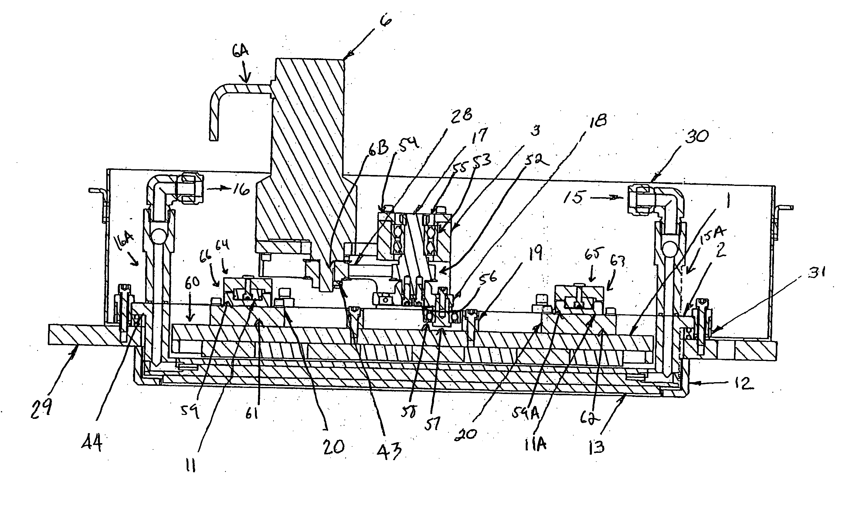
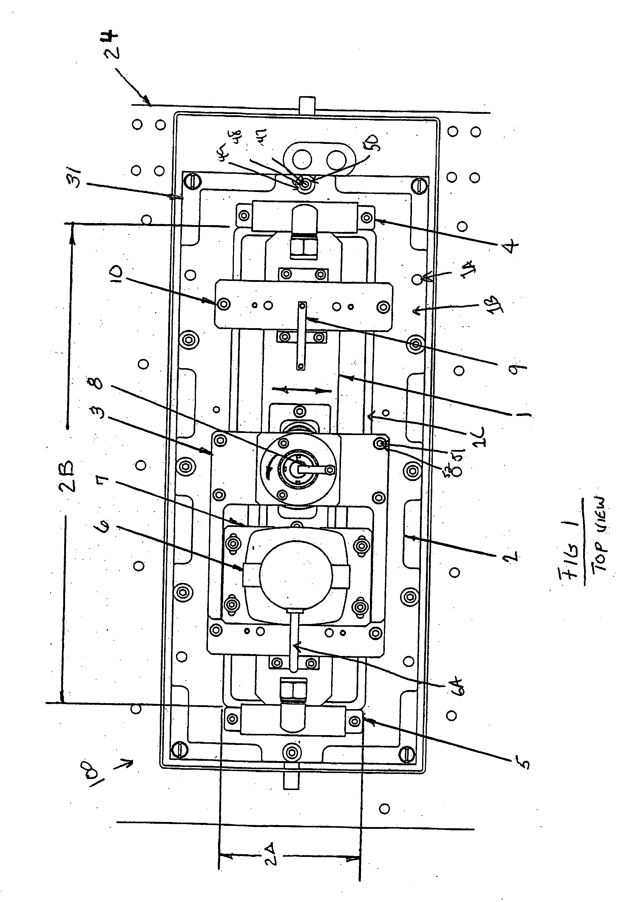
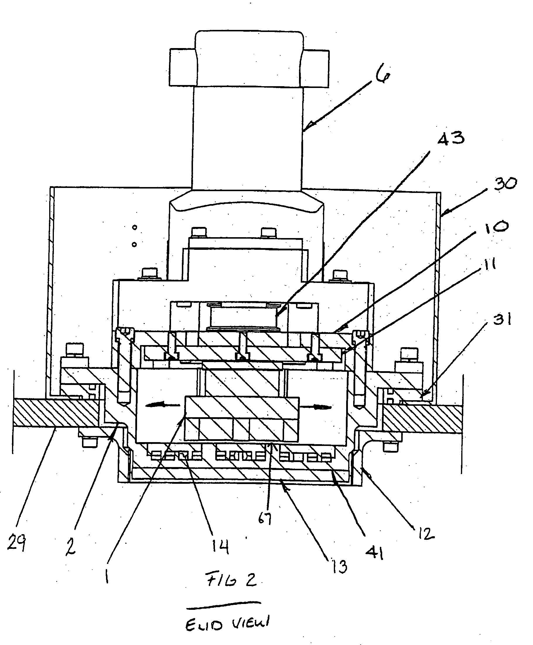
[0130] One embodiment of the present invention, an improved linear magnetron assembly for uniform target erosion, is depicted in FIG. 1. The linear magnetron 100 includes a cathode backing plate 2. The cathode backing plate 2 may be in the form of a copper plate, or manufactured from another suitable substance with similar electrical and thermal conductivity characteristics. Preferably, the cathode backing plate 2 may have terminals (not shown) for receiving an electric current. The linear magnetron assembly 100 should be adapted to be attached to a chamber top plate 29, which can be the top surface of a vacuum chamber 34 wherein the plasma deposition process will occur.

[0131] The cathode backing plate 2 may have a plurality of orifices 1A for receiving a bolt or other securing means positioned at various locations around the perimeter. These orifices around the cathode backing plate 2 are for securing the cathode backing plate 2 to a cathode insulator 31. Alternatively, the cathod...


PUM

PropertyMeasurementUnit
speedsaaaaaaaaaa
travel speedaaaaaaaaaa
temperatureaaaaaaaaaa

Abstract

A sweeping linear magnetron is described. The magnetron has a cathode backing plate, a drive housing attached to the cathode backing plate and a motor held in the drive housing. The motor drives a yoke positioned within a cut-out in the backing plate. The yoke has a magnet pack attached thereto said yoke such that the magnet pack is adapted to being moved over a target material and wherein the target material is being sputtered within a vacuum chamber onto a substrate.

Description

FIELD OF THE INVENTION [0001] The present invention relates generally to sputtering, and more particularly to a linear moving magnetron sputtering cathode, which sweeps a magnetron plasma across a target face, incorporated in a batch scanning sputter tool, for achieving nearly full-face or full-face, uniform target erosion that results in arc-free reactive deposition and high, or total, target utilization. BACKGROUND OF THE INVENTION [0002] Thin dielectric films are utilized in a wide variety of device applications, ranging from protective layers in semiconductor circuits, computer read-write heads, magnetic media, and displays, to components in optical waveguides, mirrors, filters and switches. What is common about all these applications is that these dielectric layers must be as free from defects as possible so that they provide a high level of insulation between current-carrying conductors sandwiched around them. [0003] For many applications fairly thick (several microns) dielect...

Claims


Application Information

Patent Timeline
Patent Type & Authority Applications(United States)
IPC IPC(8): C23C14/00C23C14/35H01J37/34
CPCC23C14/35H01J37/3408H01J37/3455
Inventor GUPTA, SUBHADRARUSPINI, ANDREW
Owner GUPTA SUBHADRA
Why Eureka
Try Eureka