
Lithium secondary battery and positive electrode for lithium secondary battery

a lithium secondary battery and lithium secondary battery technology, which is applied in the manufacture process of electrodes, cell components, electrochemical generators, etc., can solve the problems of high cost of cobalt, difficult to increase the actual specific capacity of the positive electrode using li-containing oxides, and considerable degradation of charge-discharge cycle characteristics

Inactive Publication Date: 2002-11-14
SANYO ELECTRIC CO LTD
View PDF2 Cites 4 Cited by
  • Summary
  • Abstract
  • Description
  • Claims
  • Application Information

AI Technical Summary

Benefits of technology

[0013] In the present invention, the oxide containing at least iron to be employed as an active material may contain potassium as described above. Further, potassium may have a concentration distributed in the thickness direction and the distribution is preferable to be gradually decreased toward the thin film surface from the interface of the substrate and the thin film. It is supposed that insertion and extraction reaction of lithium ion into and from the iron oxide is affected by the contained potassium and probably the reacting weight of lithium is decreased, so that the amounts of expansion and contraction upon the reaction is decreased. As a result, the crystal structure of the oxide is supposed to become difficult to be broken. Further, if potassium is distributed in the above-describe manner in the thickness direction, the thin film structure becomes stable near the substrate, so that the adhesion to the substrate is increased and the structure of the entire thin film becomes harder to be broken even if the charge-discharge cycles are repeated. Consequently, the decrease of the capacity can be suppressed and charge-discharge cycle characteristics are stable.
[0014] Further, the oxide containing iron and potassium may further contain carbon. The contained carbon improves the conductivity of the iron oxide thin film which is generally an insulator, so that lithium ion becomes easy to move. From such a point of view, it is assumed that the same effect is achieved by containing a conductive element or compound.
[0015] In the present invention, it is preferable to employ a substrate having electron conductivity as a substrate. Employment of the substrate having electron conductivity makes the substrate possible to function as a current collector. The substrate is preferably made of a metal or an alloy, further preferably an aluminum or an aluminum alloy. In the case of using the substrate as a current collector, its thickness is preferably thin and thus a foil made of a metal or an alloy is preferably used as the substrate.
[0016] Further, in the interface of the above-described substrate and the above-described iron oxide thin film, it is preferable for the substrate constituent and the thin film constituent to be diffused each other. Due to the diffusion of the substrate constituent and the thin film constituent, the adhesion between the thin film and the substrate is improved and an effect of suppression of the reaction of the iron oxide and lithium ion is supposed to be caused similarly to the above-described effect of containing potassium.
[0017] Examples of a method for forming an iron oxide thin film of the present invention are, as described above, various vacuum processes, a spraying method, a plating method, and a method in combination with these method. Especially, a sputtering method, a reactive deposition method, a vacuum deposition method, and a chemical vapor deposition (CVD) method are preferable. That is because the mutual diffusion of the substrate constituent and the thin film constituent is increased depending on the effect of the temperature at the time of forming thin film and because the thin film becomes easy to grow in columnar structure. Further, it makes easy to control the composition, for example, in the thickness direction by controlling the film forming conditions. Further, it also makes possible to form a mixed layer (a mutually diffused region) in the interface between the substrate and the thin film, control the crystallinity (the orientation) of the thin film, and control the growth direction (the growth promotion in the columnar direction) by forming under the conditions where ions are radiated, for example, to the thin film growth surface. As a practical method for radiating ions, there are a method for radiating ion beam of such as Ar and oxygen while the deposition materials reach the substrate surface, and a method for attracting ions such as Ar and oxygen by applying practically negative voltage to the substrate to collide the ion against the substrate.

Problems solved by technology

However, a lithium-containing oxide such as LiCoO.sub.2 is known as a material whose crystal structure is broken and whose charge-discharge cycle characteristics are considerably deteriorated if Li is completely pulled out.
Consequently, it is difficult to increase the actual specific capacity of the positive electrode using such as Li-containing oxide.
Further, since cobalt reserves are in small amounts and thus cobalt is expensive, a positive electrode material in place of that is required.
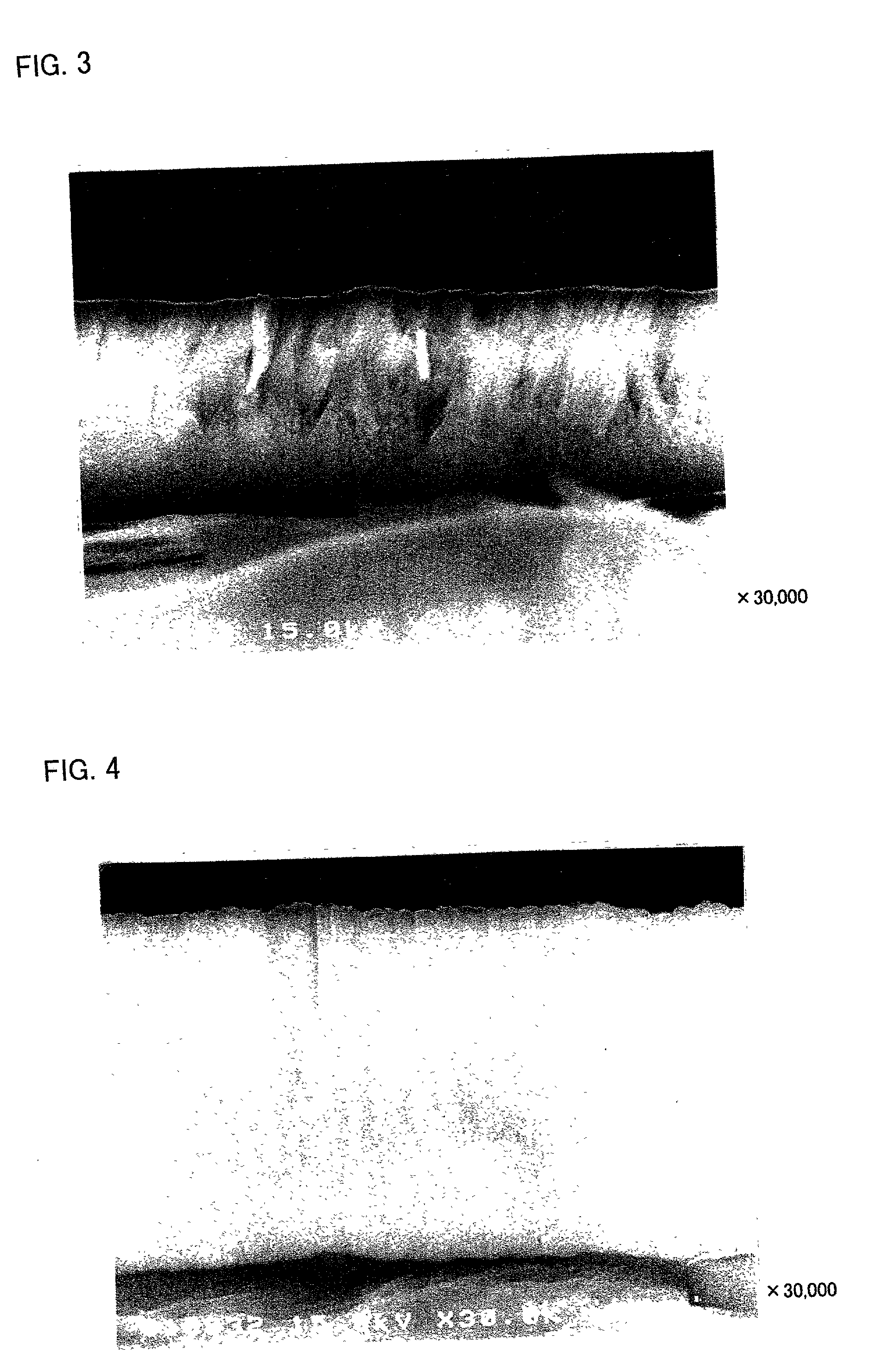
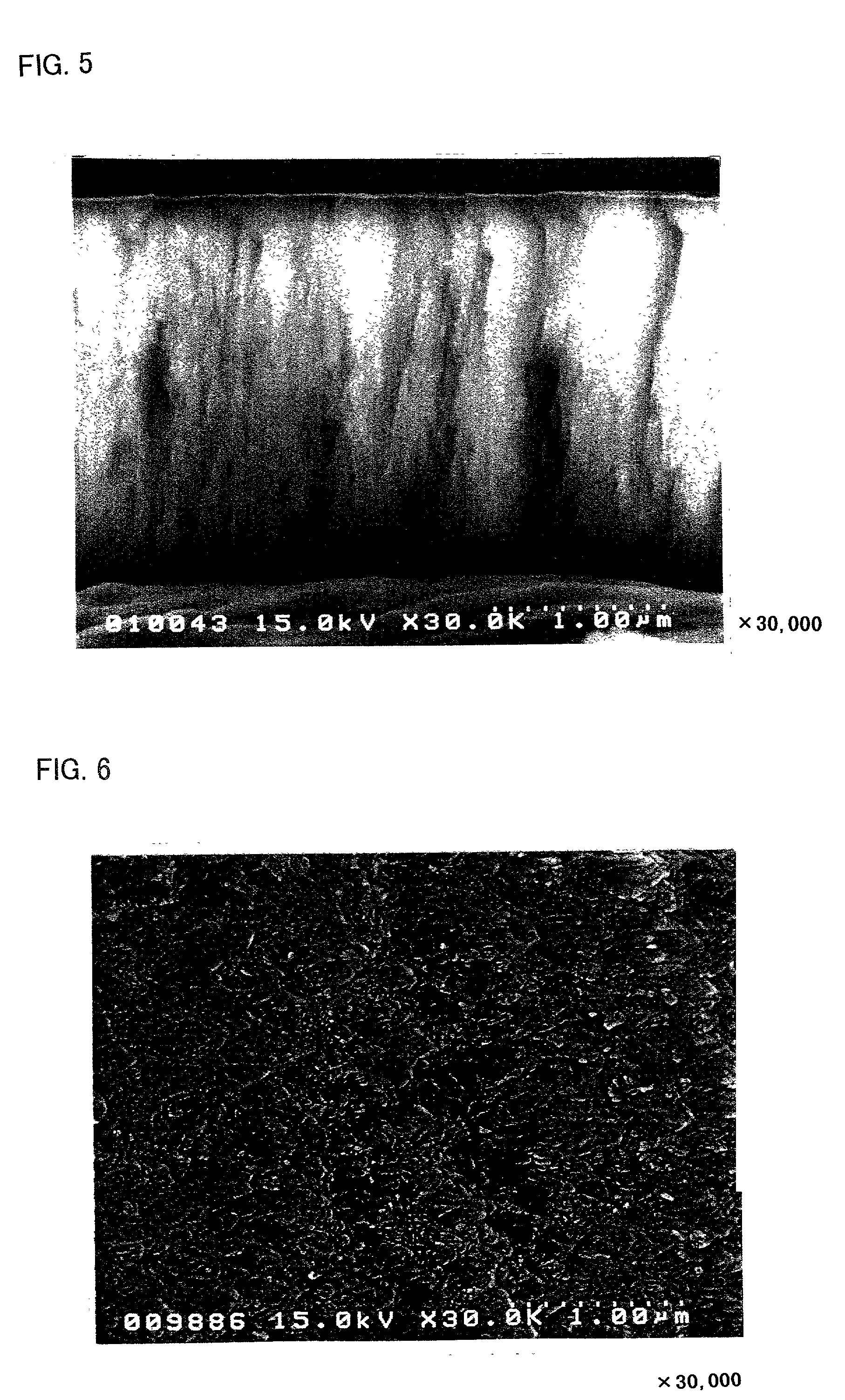
Although the detailed reasons are not made clear, it is supposed that due to the columnar structure, the expansion and contraction of the positive active material during charge and discharge take place in the thickness direction and as a result, even if the charge-discharge cycles are repeated, the structure of the entire thin film becomes difficult to be broken and decrease of the capacity becomes slight.
As a result, the crystal structure of the oxide is supposed to become difficult to be broken.
Further, if potassium is distributed in the above-describe manner in the thickness direction, the thin film structure becomes stable near the substrate, so that the adhesion to the substrate is increased and the structure of the entire thin film becomes harder to be broken even if the charge-discharge cycles are repeated.

Method used


Image

  • Lithium secondary battery and positive electrode for lithium secondary battery
  • Lithium secondary battery and positive electrode for lithium secondary battery
  • Lithium secondary battery and positive electrode for lithium secondary battery

Examples


experiment 1

[0040] (Experiment 1)

[0041] [Production of Positive Electrode]

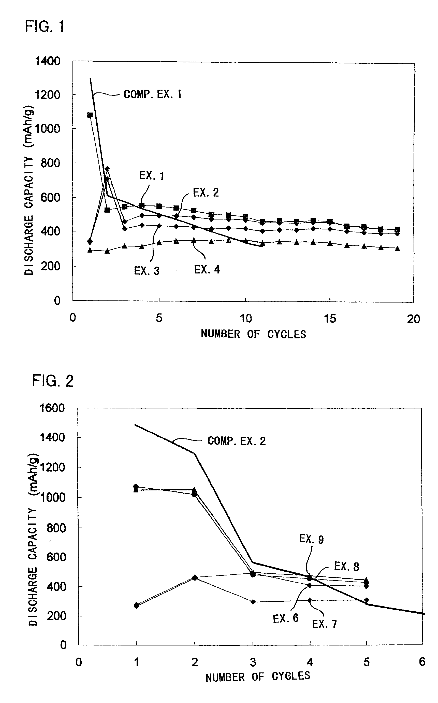
[0042] A thin film was formed on an aluminum foil (the thickness of 20 .mu.m) using a target of K.sub.1.33Fe.sub.11O.sub.17 by RF sputtering method. The film forming conditions were shown in Table 1.

[0043] As the target shown in Table 1, those with a diameter of 10.2 cm (4 inch) and a thickness of 5 mm were employed. As the carbon chips put on the targets, those with a diameter of 10 mm and a thickness of 1 mm, and as the iron chips, those with 10 mm square and a thickness of 1 mm were employed in the number shown in Table 1, respectively. As the carbon chips, pellets made from powdery graphite were employed. As the iron chips, iron plates with the above-described shapes were employed.

1 TABLE 1 loaded sputtering sputtering electric gas flow gas flow target chip power rate Ar rate O.sub.2 Ex. 1 K.sub.1.33Fe.sub.11O.sub.17 none 350 W 100 sccm 0 sccm Ex. 2 K.sub.1.33Fe.sub.11O.sub.17 3 carbon 350 W 100 sccm 0 sccm chips Ex. ...

experiment 2

[0062] (Experiment 2)

[0063] [Production of Positive Electrode]

[0064] A thin film (a ferrite thin film) constituted of Fe and O was produced on an aluminum foil (the thickness of 20 .mu.m) by a reactive deposition method. In the reactive deposition method, O.sub.2 was introduced into a vacuum chamber and the Fe deposition material was melted and evaporated by an electron beam (EB) gun to form the ferrite thin film on the aluminum foil, i.e. a substrate (Examples 5-7).

[0065] Further, also by an ion-assisting reactive deposition method, in which simultaneously with the deposition of Fe, ion beam was radiated toward the aluminum foil, an iron oxide (ferrite) thin film was formed (Examples 8 and 9).

[0066] Table 3 shows the respective film forming conditions.

3 TABLE 3 film- deposition reactive ion beam forming deposition speed gas O.sub.2 radiation method material (nm / sec.) flow rate conditions Ex. 5 reactive Fe 0.25-0.40 10 sccm no radiation Ex. 6 deposition 0.20-0.30 20 sccm Ex. 7 metho...


PUM

PropertyMeasurementUnit
Fractionaaaaaaaaaa
Fractionaaaaaaaaaa
Fractionaaaaaaaaaa

Abstract

A lithium secondary battery comprises a negative electrode containing lithium metal or a material previously storing lithium as an active material, a positive electrode containing a positive active material, and an electrolyte containing a non-aqueous electrolyte solution. The positive active material is a thin film formed by depositing on a substrate from vapor phase or liquid phase and including an oxide containing at least iron as a main constituent by a sputtering method, a reactive deposition method, a vacuum deposition method, a chemical vapor deposition method, a spraying method, a plating method, or a method in combination of these methods.

Description

[0001] 1. Field of the Invention[0002] The present invention relates to a lithium secondary battery and a positive electrode of the lithium secondary battery.[0003] 2. Related Art[0004] In recent years, a lithium secondary battery referred to as a lithium ion battery has widely been used for power sources of cellular phones and personal computers. Generally, a lithium secondary battery which has recently practically been used has a weight energy density of about 150 Wh / kg and is required to further densify weight energy density.[0005] The lithium secondary battery in practical use employs a carbon-based material such as graphite for the negative electrode, a lithium-containing oxide such as LiCoO.sub.2 for the positive electrode, and an organic solvent, for example, cyclic carbonate such as ethylene carbonate, a chain carbonate such as dimethyl carbonate and the like, in which an electrolyte salt such as LiPF.sub.6 is dissolved, for the electrolyte solution. In such kind of lithium ...

Claims


Application Information

Patent Timeline
IPC IPC(8): H01M4/13H01M4/131H01M4/139H01M4/66H01M4/1391H01M4/52H01M10/05H01M10/052H01M10/0566
CPCH01M4/04H01M4/485H01M4/525Y02E60/122H01M10/052H01M10/0525H01M2004/028H01M4/661Y02E60/10
Inventor KUSUMOTO, YASUYUKIFUJIMOTO, MASAHISAFUJITANI, SHINDOMOTO, YOICHIJITO, DAIZOTARUI, HISAKI
Owner SANYO ELECTRIC CO LTD
Learn More