Layer configuration

a lithiumion battery and layer technology, applied in the field of layer configuration, can solve the problems of limited performance value and many electrolytes that are not without environmental problems, and achieve the effects of increasing ion storage capacity, increasing electrical conductivity, and improving ion storage capacity

Inactive Publication Date: 2014-08-14
ROBERT BOSCH GMBH
View PDF7 Cites 0 Cited by
  • Summary
  • Abstract
  • Description
  • Claims
  • Application Information

AI Technical Summary

Benefits of technology

[0019]When selecting the appropriate auxiliary, the intended use of the corresponding layer is taken into account in particular. If the auxiliary should be situated in the organic matrix of an electrode layer, for example, then carbon nanotubes in particular are advantageous since they are capable of increasing the electrical conductivity. In this function, carbon nanotubes may be situated in both electrode layers regardless of whether the electrode is a cathode or an anode. In an anode layer, they also help to increase the ion storage capacity. For the case of an anode, materials from the aforementioned group of anode storage materials are also advantageous, whereas in the case of a cathode, materials from the aforementioned group of cathode storage materials are preferred. The chemical potential with respect to lithium in particular is optimized by the auxiliaries identified above or the ion storage capacity is improved. Depending on the desired application, a suitable combination of auxiliaries may be provided.
[0020]Furthermore, it is preferred in particular that the at least one auxiliary is present in a quantity of up to 30 wt %. The desired effects are therefore achievable without having a significant negative influence on the processability of the organic matrix or the manufacture of the corresponding layers.
[0021]Within the context of an additional advantageous embodiment of the configuration according to the present invention, the configuration includes a substrate. The substrate may impart an improved stability to the configuration, in particular for the case when the individual layers have a low stability. This may be the case due to the design of very thin layers, for example.
[0022]Within the context of another advantageous embodiment of the configuration according to the present invention, a current collector layer is situated on the side of the top and / or bottom electrode layer(s) opposite the electrolyte layer. The current collector layer functions to improve the electrical conductivity of the corresponding electrode layer and also to provide a suitably designable contact of the electrode layer. For example, the current collector layer may be made of gold, platinum, aluminum, alloys or other materials having a good electrical conductivity.
[0023]The present invention also relates to an energy store such as in particular a rechargeable lithium-ion battery, which includes a configuration according to the present invention. The configuration according to the present invention is suitable for the assembly of a rechargeable lithium-ion battery in particular. The rechargeable lithium-ion battery according to the present invention is particularly simple to manufacture and its properties are readily adaptable to the intended use.

Problems solved by technology

However, the performance values were usually limited due to the small quantities of active material in the thin, two-dimensional layers, but such thin-film rechargeable batteries are already used in energy-saving equipment.
In addition, many electrolytes are not without problems for the environment.

Method used


Image

  • Layer configuration
  • Layer configuration

Examples


Embodiment Construction

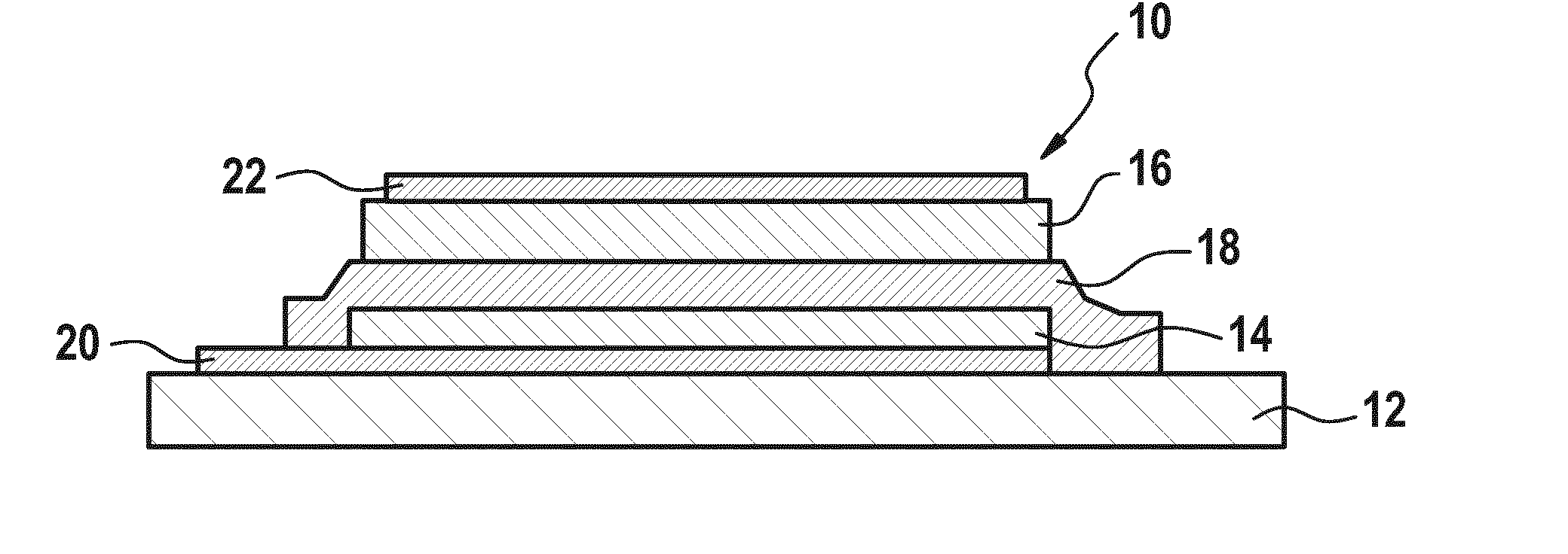
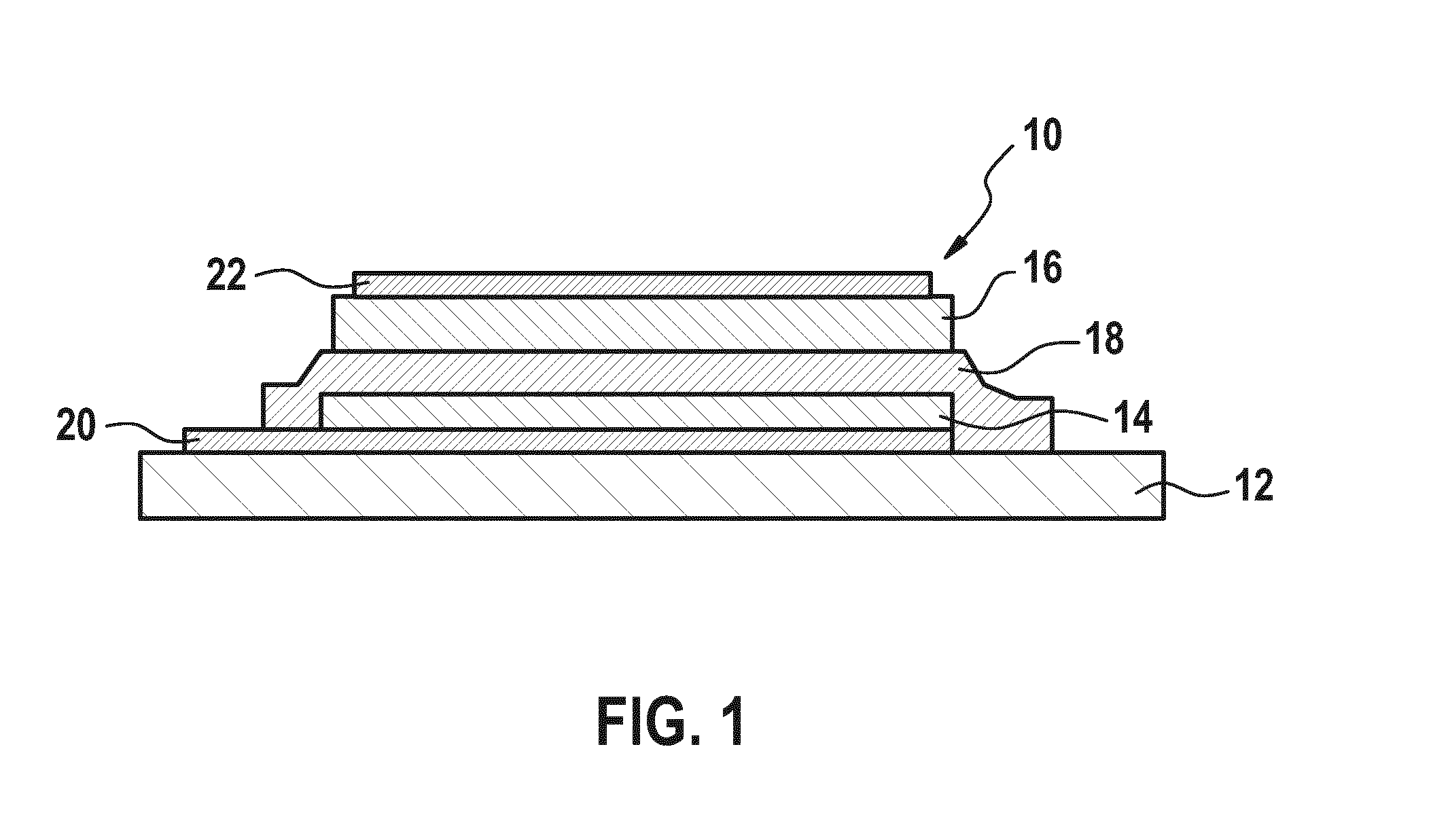
[0025]FIG. 1 shows a specific embodiment of configuration 10 according to the present invention. Configuration 10 may be part of a rechargeable lithium-ion battery, for example.

[0026]Configuration 10 according to the present invention may include a substrate 12 as a carrier. Substrate 12 may function to impart greater stability to the layers, as described below. However, substrate 12 is only optional and need not necessarily be present. For example, substrate 12 may be omitted if the layers have sufficient stability. Substrate 12 is made of a semiconductor material or a MEMS material, for example, such as silicon. Furthermore, substrate 12 may be made of a polymer or a metal. It is advantageous if the surface of substrate 12 is designed to be electrically insulating. Furthermore, if the material of substrate 12 is not electrically insulating per se, an insulation layer may be situated on substrate 12. This insulation layer may be a dielectric passivation layer, for example.

[0027]Con...


PUM

PropertyMeasurementUnit
ionic conductivityaaaaaaaaaa
organicaaaaaaaaaa
power densityaaaaaaaaaa

Abstract

A configuration includes at least three successive layers, the three layers having a top electrode layer, a bottom electrode layer, and an electrolyte layer situated between the top electrode layer and the bottom electrode layer. At least the electrolyte layer and one of the top electrode layer or the bottom electrode layer have an organic matrix, and the organic matrix of the electrolyte layer has an ionic conductivity in a range of ≧10−6 S/cm. Such a configuration is suitable in particular for forming a rechargeable lithium-ion battery and permits simple and cost-effective manufacturing and good adaptability to the desired application.

Description

FIELD OF THE INVENTION[0001]The present invention relates to a layer configuration including two electrode layers and an electrolyte layer situated between the electrode layers. The present invention relates in particular to a rechargeable lithium-ion battery including the layer configuration.BACKGROUND INFORMATION[0002]Lithium-ion batteries, i.e., rechargeable lithium-ion batteries, are in widespread use today. They are preferred for use in portable devices such as cell phones or mobile computers in particular. Their advantages lie in their high power density and capacitance density in particular. Attempts have already been made to manufacture rechargeable lithium-ion batteries by using semiconductor methods in thin-film technology. However, the performance values were usually limited due to the small quantities of active material in the thin, two-dimensional layers, but such thin-film rechargeable batteries are already used in energy-saving equipment.[0003]One interesting perspect...

Claims


Application Information

Patent Timeline
Patent Type & Authority Applications(United States)
IPC IPC(8): H01M10/0565H01M10/0525
CPCH01M4/624H01M10/0525H01M10/0565Y02E60/122Y02E60/10Y02P70/50
Inventor PIRK, TJALFGHAHREMANPOUR, MEHRANSAEGEBARTH, JOACHIMBOGNER, MARTINSANDMAIER, HERMANN
Owner ROBERT BOSCH GMBH
Why Eureka
Try Eureka