

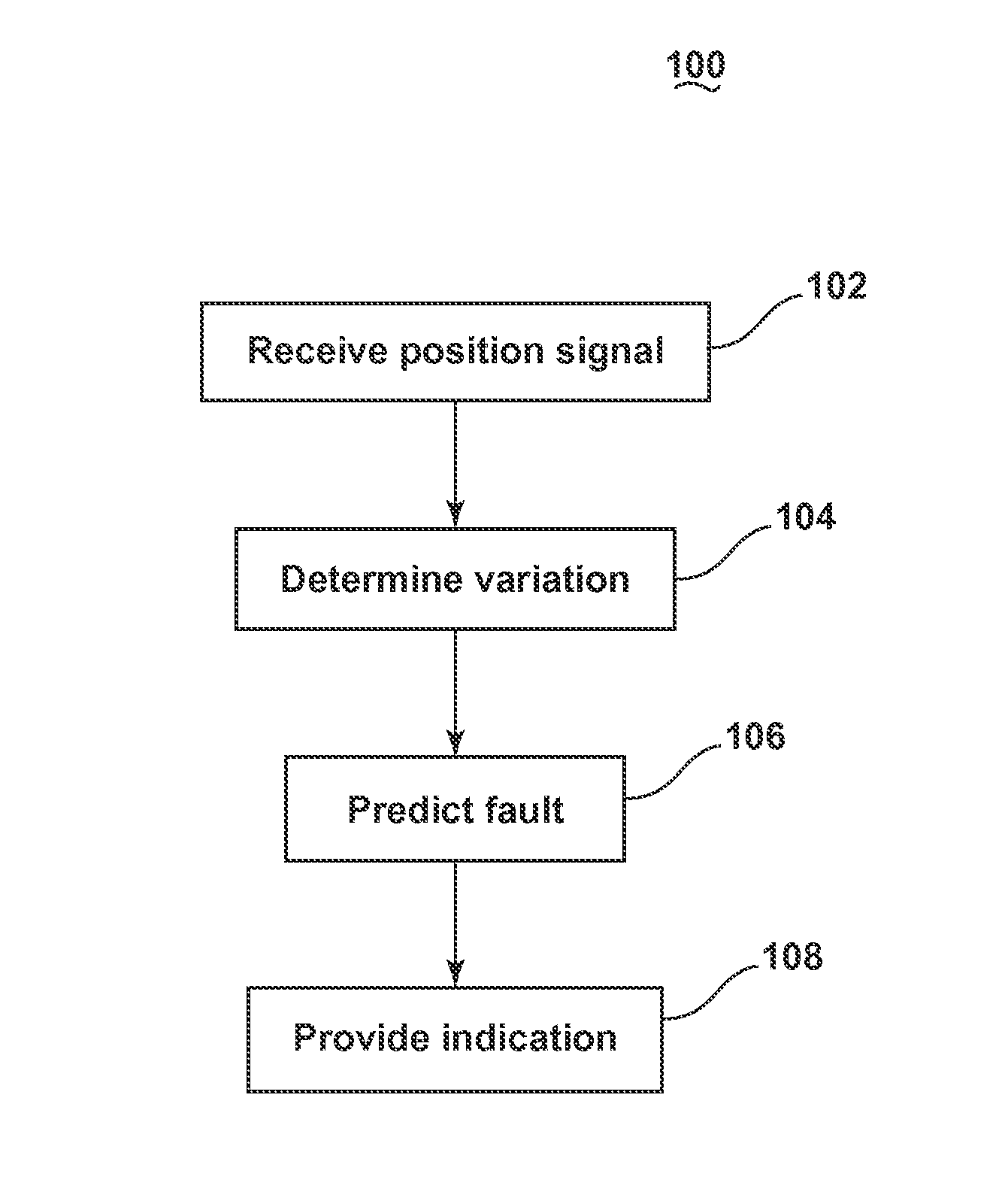
Method for predicting faults in an aircraft thrust reverser system
a thrust reverser and fault technology, applied in the direction of engine fuction, engine control, structural/machine measurement, etc., can solve problems such as loss of revenu
- Summary
- Abstract
- Description
- Claims
- Application Information
AI Technical Summary
Benefits of technology
Problems solved by technology
Method used
Image

Examples
Embodiment Construction
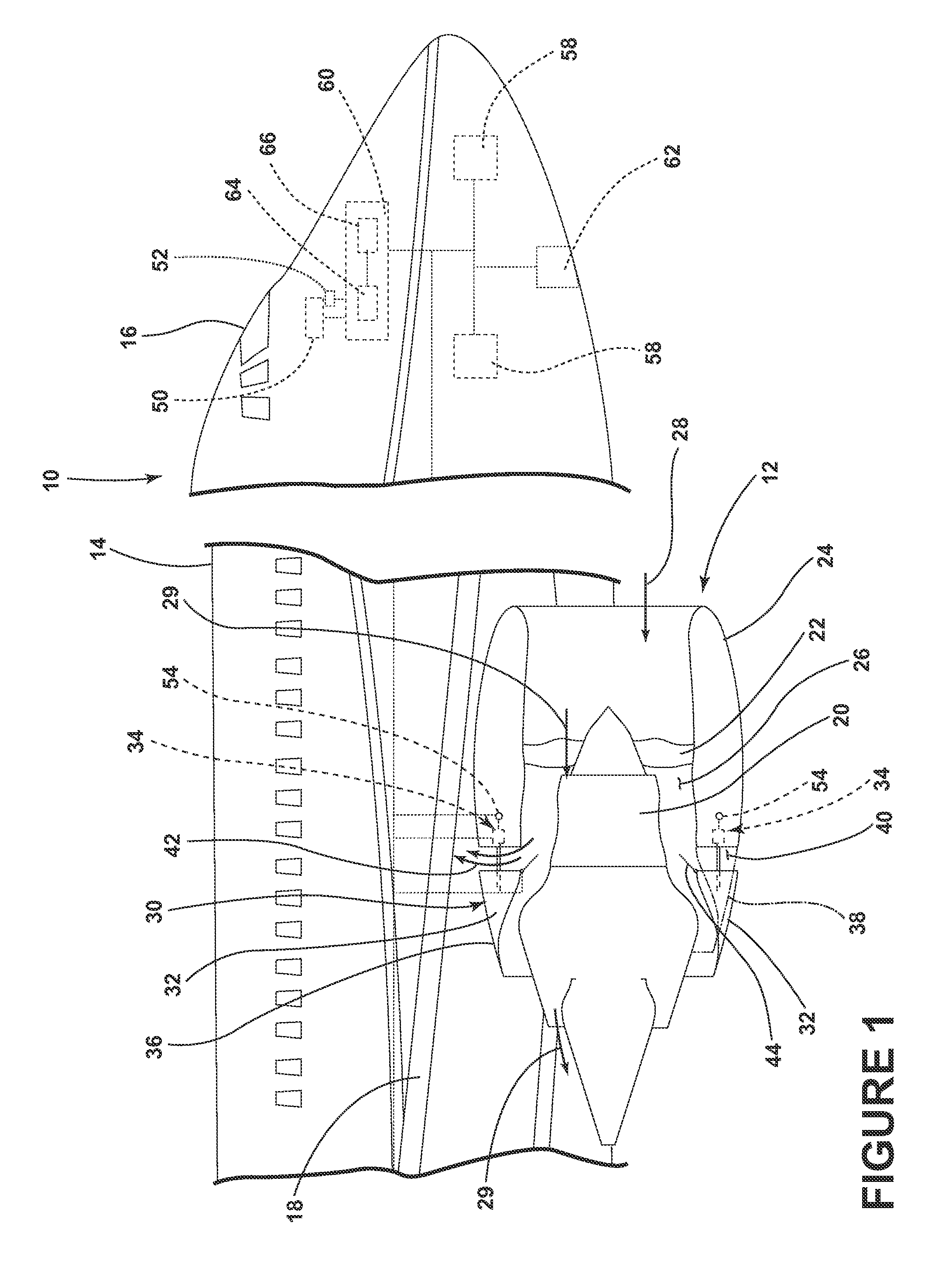
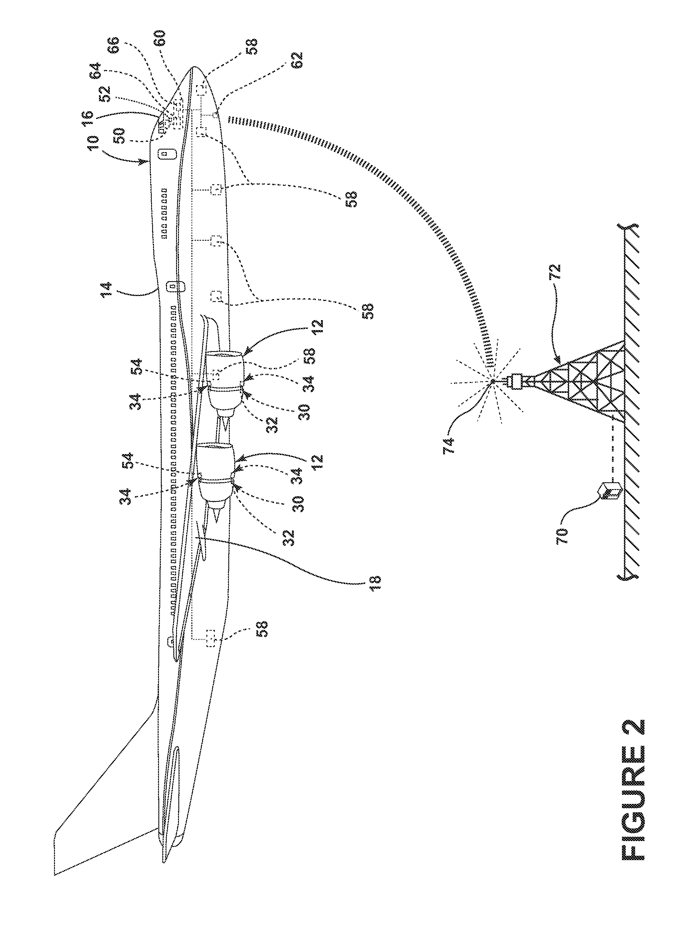
[0008]FIG. 1 schematically depicts a portion of an aircraft 10 that may execute embodiments of the invention and may include one or more engine assemblies 12 coupled to a fuselage 14, a cockpit 16 positioned in the fuselage 14, and wing assemblies 18 extending outward from the fuselage 14. A turbine engine 20, a fan assembly 22, and a nacelle 24 may form portions of each of the engine assemblies 12. Portions of the nacelle 24 have been cut away for clarity. The nacelle 24 surrounds the turbine engine 20 and defines an annular air flow path or annular bypass duct 26 through the engine assembly 12 to define a generally forward-to-aft bypass air flow path as schematically illustrated by the arrow 28. Combustion airflow is schematically illustrated by the arrows 29.
[0009]A thrust reverser system 30 includes at least one thrust reverser 32 having at least one actuator 34 for moving the at least one thrust reverser 32 between a deployed or reversing position 36 and a retracted or stowed p...
PUM
 Abstract
Description
Claims
Application Information