Supply method for liquid and supply apparatus

a technology of supply apparatus and liquid, which is applied in the direction of water supply installation, transportation and packaging, and inorganic non-surface active detergent compositions, etc. it can solve the problems of affecting the quality of the surface of the cleaned electronic parts, reducing product yield, and difficulty in preparing and supplying wash water having a constant concentration to the use point, and achieves low cost and special

Active Publication Date: 2014-08-21
KURITA WATER INDUSTRIES LTD
View PDF12 Cites 3 Cited by
  • Summary
  • Abstract
  • Description
  • Claims
  • Application Information

AI Technical Summary

Benefits of technology

[0029]According to the present invention, even when the amount of use of the solution at the use point changes, the change is absorbed by the retention portion, whereby the solution having a predetermined concentration can be stably supplied to a use point. Such a retention portion is advantageous in terms of space saving since the retention portion can be formed by using, for example, a long pipe portion or a large-diameter portion of a pipe having no gas-liquid interface. Such a retention portion can be installed in existing equipment at a low cost by only slightly modifying an intermediate portion of a supply pipe.
[0030]The supply method for liquid and the supply apparatus according to the present invention are use

Problems solved by technology

Specifically, if the concentration of the cleaning component in the wash water is not constant, the quality of the surfaces of the cleaned electronic parts is affected, decreasing product yields.
In terms of a waste-liquid disposal cost and environmental problems, however, only an amount of wash water required at the use point is desirably supplied without producing excess water that needs disposal.
However, preparing and supplying wash water having a constant concentration to the use point is difficult by only contro

Method used


Image

  • Supply method for liquid and supply apparatus
  • Supply method for liquid and supply apparatus
  • Supply method for liquid and supply apparatus

Examples


example 1

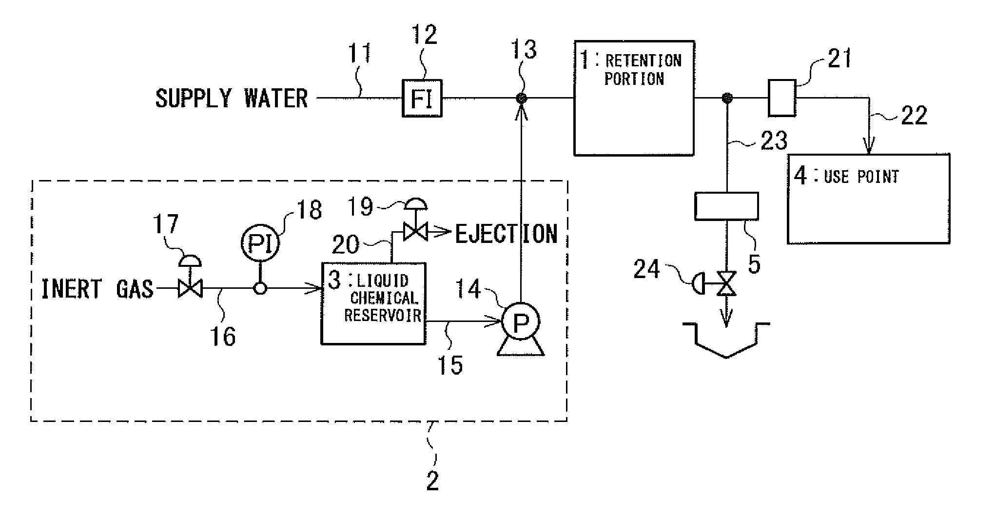
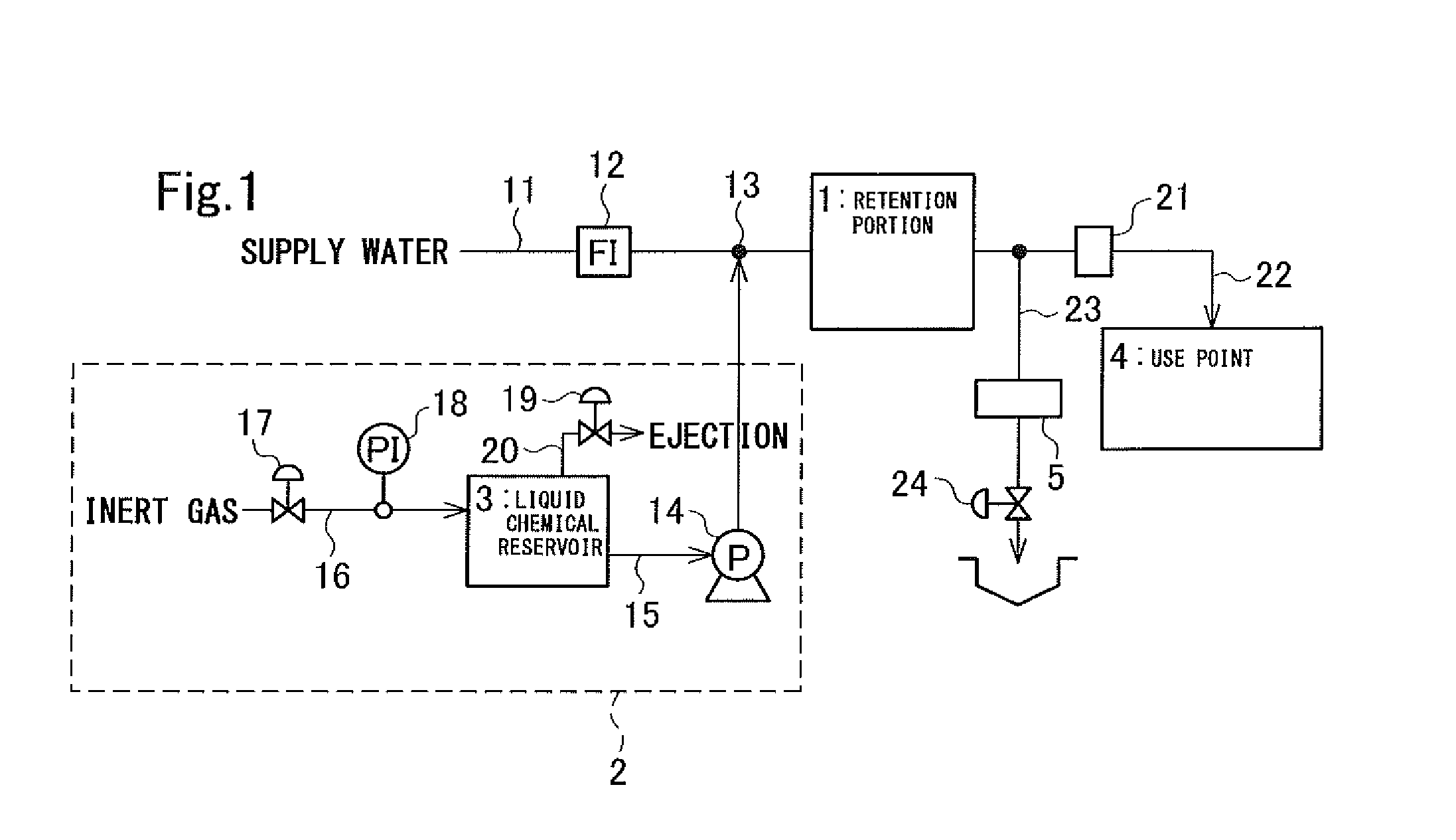
[0061]Wash water was supplied to the use point by the wash water supply apparatus illustrated in FIG. 1 under the following conditions.

[0062]Supply water: ultrapure water

[0063]Flow rate of supply water: 1 to 30 L / min

[0064]Chemical agent: ammonia

[0065]Concentration of chemical agent of liquid chemical in liquid chemical reservoir: 1000 mg / L

[0066]Concentration at injection (concentration of chemical agent in wash water): 10 mg / L

[0067]Liquid-chemical injection pump: “EHN-B11” from IWAKI Co., Ltd.

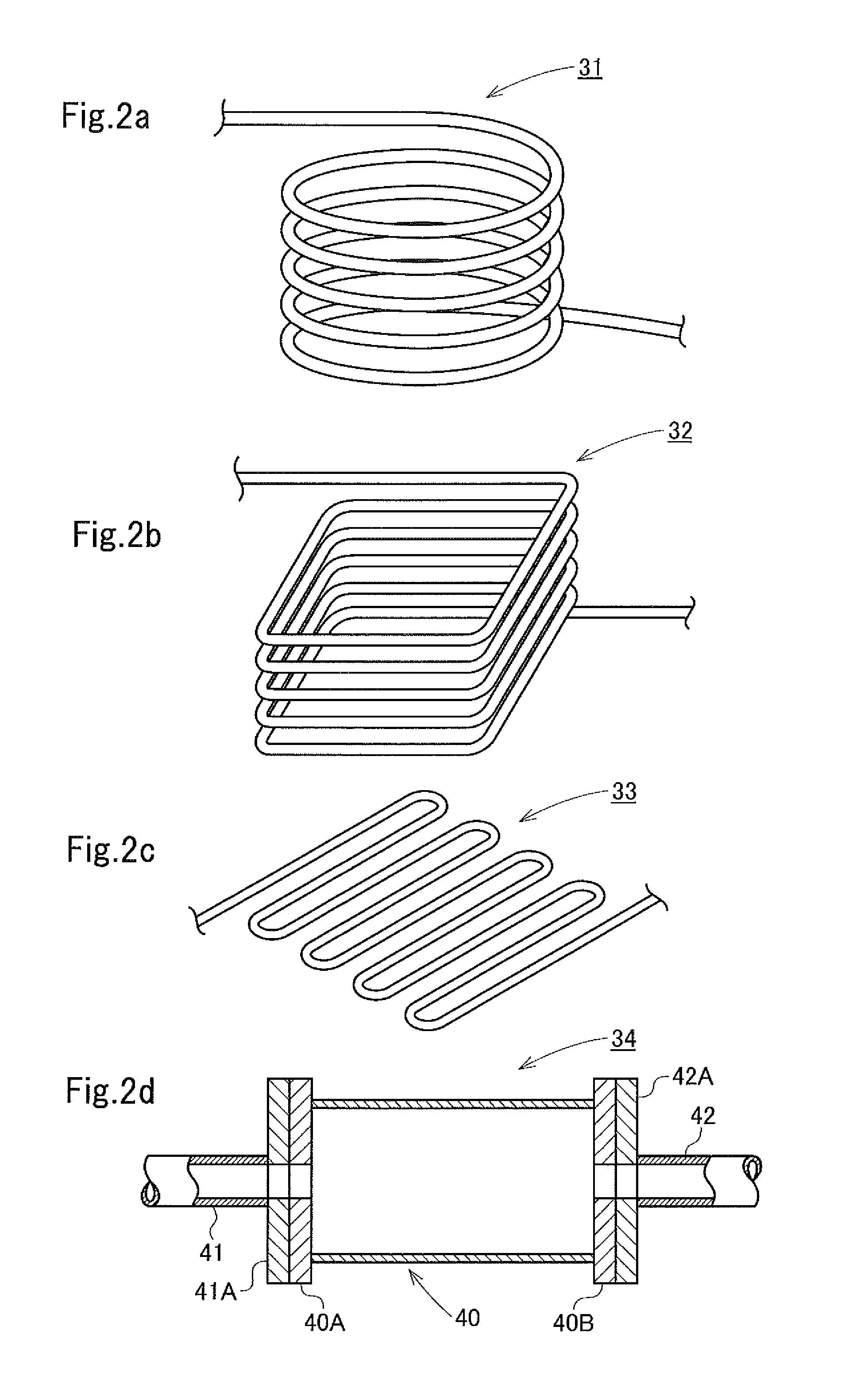
[0068]Retention portion: large-diameter pipe illustrated in FIG. 2d

[0069]Filter: “Ultipleat SP DR” from Nihon Pall Ltd. (pore diameter 30 nm)

[0070]In this example, in order to increase an effect of the change in amount of use of water at the use point so that the degree of the change in concentration of the chemical agent in wash water due to the change in flow rate is clarified, the flow rate of supply water from the pipe 11 was changed within the range of 1 to 30 L / min and the injection of t...


PUM


Abstract

A solution having a predetermined concentration is stably supplied to a use point, at which the amount of use of the solution changes, by only modifying currently-used equipment at a low cost and in a space-saving manner. In order to supply a solution containing a solute at a predetermined concentration from a preparation portion of the solution to a use point through a supply pipe, a retention portion that has no gas-liquid interface and at which the solution is retained is provided at an intermediate portion of the supply pipe. Even when the amount of use of the solution at the use point changes, the change is absorbed by the retention portion, whereby a solution having a predetermined concentration can be stably supplied to the use point. Such a retention portion is advantageous in terms of space saving since the retention portion can be formed by using, for example, a long pipe portion or a large-diameter portion of a pipe having no gas-liquid interface. Such a retention portion can be installed in existing equipment at a low cost by only slightly modifying an intermediate portion of a supply pipe.

Description

FIELD OF INVENTION[0001]The present invention relates to a supply method for liquid and a supply apparatus, and particularly to a method and an apparatus for stably supplying wash water containing a cleaning component at a low concentration, the cleaning component being used in cleaning of electronic parts or the like requiring high purity, surface reforming, or a surface protection process, examples of the cleaning component including acid, alkali, or a gas such as ozone or hydrogen, and examples of the electronic parts requiring high purity including a silicon wafer for a semiconductor device and a glass substrate for a flat panel display.BACKGROUND OF INVENTION[0002]To date, a highly concentrated liquid chemical or cleanser has been used in cleaning of substrates serving as electronic parts, surface reforming, or a surface protection process, typically in the RCA clean, and a large amount of pure water or ultrapure water has been used for rinsing the solution or the cleanser. For...

Claims


Application Information

Patent Timeline
IPC IPC(8): F17D1/08
CPCF17D1/08H01L21/67017H01L21/67051Y10T137/0324Y10T137/3021Y10T137/87652C11D7/02H01L21/304E03C1/00
Inventor TOKOSHIMA, HIROTOISHIWATA, KAZUYA
Owner KURITA WATER INDUSTRIES LTD
Why Eureka
Try Eureka