Fiber optic acoustic sensor arrays, fiber optic sensing systems and methods of forming and operating the same

Inactive Publication Date: 2014-08-21
AVALON SCI
View PDF10 Cites 15 Cited by
  • Summary
  • Abstract
  • Description
  • Claims
  • Application Information

AI Technical Summary

Benefits of technology

[0006]To meet this and other needs, and according to an exemplary embodiment of the present invention, a fiber optic acoustic sensing array is provided. The fiber optic acoustic sensing array includes a core strength member and an optical fiber wound on the core strength member to create an extended, dy

Problems solved by technology

However, such sonar systems typically suffer from a number of drawbacks (e.g., such systems may be easily discovered and defeated, such systems may cause harm to m

Method used


Image

  • Fiber optic acoustic sensor arrays, fiber optic sensing systems and methods of forming and operating the same
  • Fiber optic acoustic sensor arrays, fiber optic sensing systems and methods of forming and operating the same
  • Fiber optic acoustic sensor arrays, fiber optic sensing systems and methods of forming and operating the same

Examples


Embodiment Construction

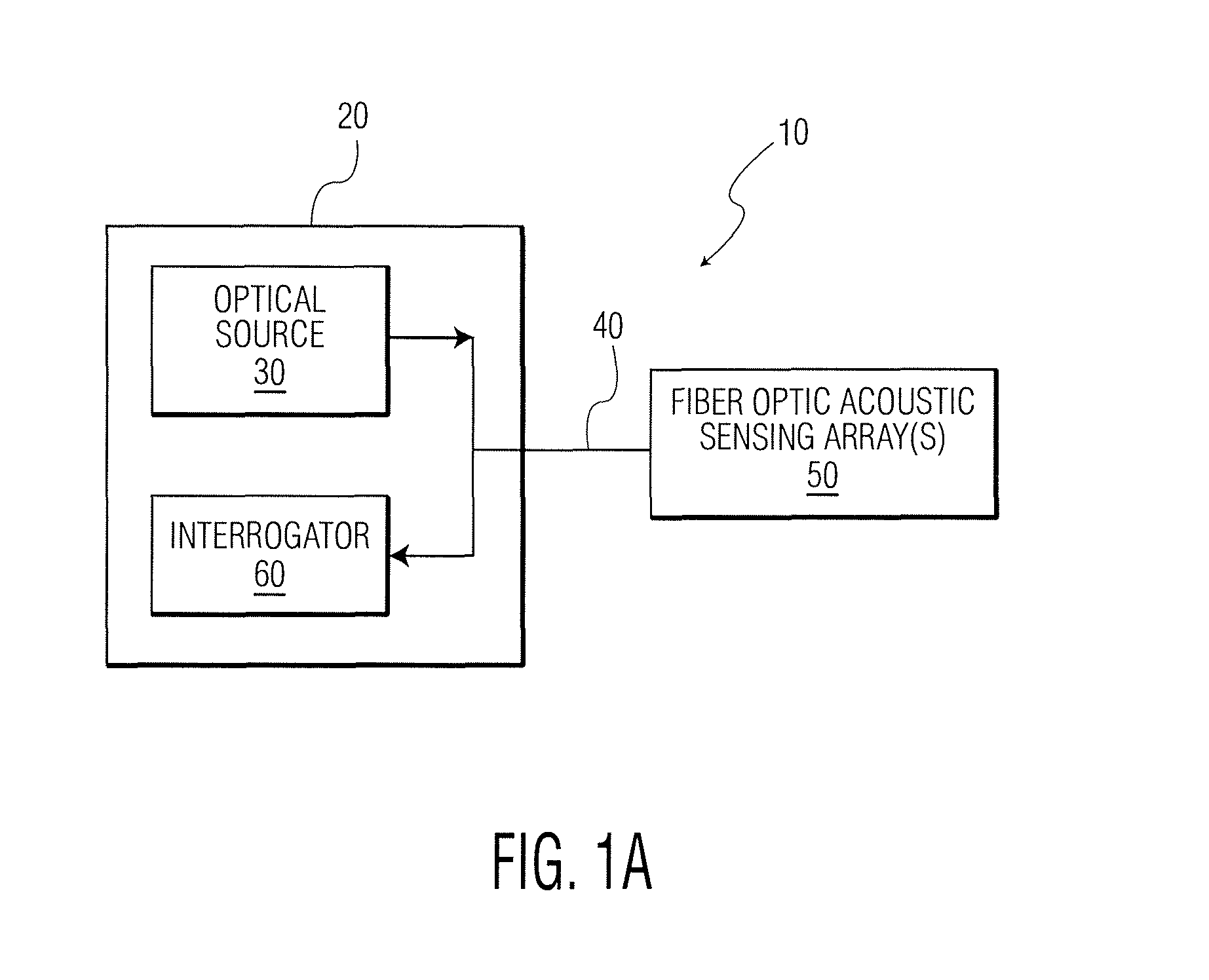
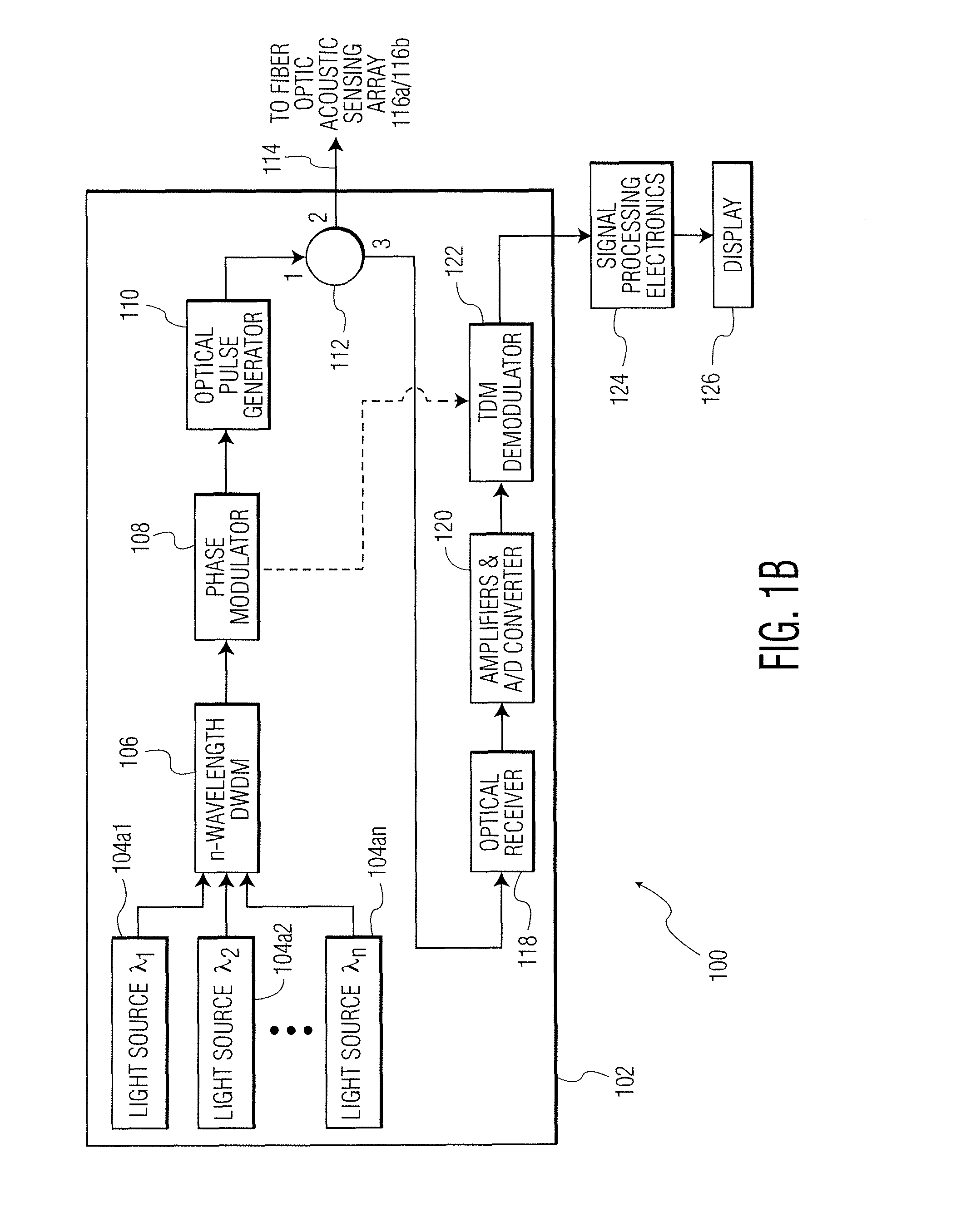
[0026]FIG. 1 illustrates an exemplary fiber optic sensing system 10. Fiber optic sensing system 10 includes an optics assembly 20. Optics assembly 20 includes optical source 30 (e.g., a modulated laser, etc.) and an interrogator 60. Of course, optics assembly 20 may include additional elements (e.g., opto-electronics elements) as desired in the given application, for example, to enable multiple wavelength operation. Optical signals are transmitted from optical source 30, along a lead cable 40, and to a fiber optic acoustic sensing array 50. Optical signals are returned from fiber optic acoustic sensing array 50, along lead cable 40, and are received by interrogator 60 for further processing. As will be appreciated by those skilled in the art, optics assembly 20 and fiber optic acoustic sensing array 50 may vary considerably within the scope of the present invention. FIG. 1B illustrates an exemplary optics assembly 102 (which is an example of optics assembly 20), and FIGS. 1C-1D illu...


PUM

PropertyMeasurementUnit
Lengthaaaaaaaaaa
Thicknessaaaaaaaaaa
Diameteraaaaaaaaaa

Abstract

A fiber optic acoustic sensing array. The fiber optic acoustic sensing array includes a core strength member and an optical fiber wound on the core strength member. The optical fiber includes a plurality of Fiber Bragg Gratings, and is coated with a voided plastic coating. An outer jacket covers the optical fiber coated with the voided plastic coating. Also disclosed are fiber optic sensing systems, methods of forming a fiber optic acoustic sensing array, and methods of operating fiber optic sensing systems.

Description

RELATED APPLICATION[0001]This application claims the benefit of priority to U.S. Provisional Patent Application Ser. No. 61 / 766,919, filed on Feb. 20, 2013, the contents of which are incorporated in this application by reference.TECHNICAL FIELD[0002]The field of the invention relates to fiber optic sensing systems, and more particularly, to improved fiber optic acoustic sensing arrays for use in such fiber optic sensing systems.BACKGROUND OF THE INVENTION[0003]It is sometimes desirable to detect the presence of swimmers or watercraft. For example, it may be desirable to detect swimmers using Self-Contained Underwater Breathing Apparatus (SCUBA) or Closed Circuit Rebreathers (CCRs), where the swimmers might be intent on attacking an installation, or intruding upon the land nearby the relevant body of water. Existing swimmer detection systems generally utilize active sonar systems. However, such sonar systems typically suffer from a number of drawbacks (e.g., such systems may be easil...

Claims


Application Information

Patent Timeline
IPC IPC(8): G01H9/00G01J1/04
CPCG01J1/0425G01H9/004Y10T29/49117
Inventor GOLDNER, ERIC LEEDEMETZ, FREDERICK C.
Owner AVALON SCI
Why Eureka
Try Eureka