Light source apparatus and projector
a technology of light source and projector, which is applied in the direction of lighting and heating equipment, instruments, transportation and packaging, etc., can solve the problems of bringing adverse effects, high possibility of speckle, and problematic speckl
- Summary
- Abstract
- Description
- Claims
- Application Information
AI Technical Summary
Benefits of technology
Problems solved by technology
Method used
Image

Examples
first embodiment
[0042]Hereinafter, a projector according to the first embodiment of the invention will be described with reference to FIGS. 1 to 5B. In addition, in all of the following drawings, for better understanding of the drawings, dimensions or proportions of respective constituent elements are made to be appropriately different from each other.
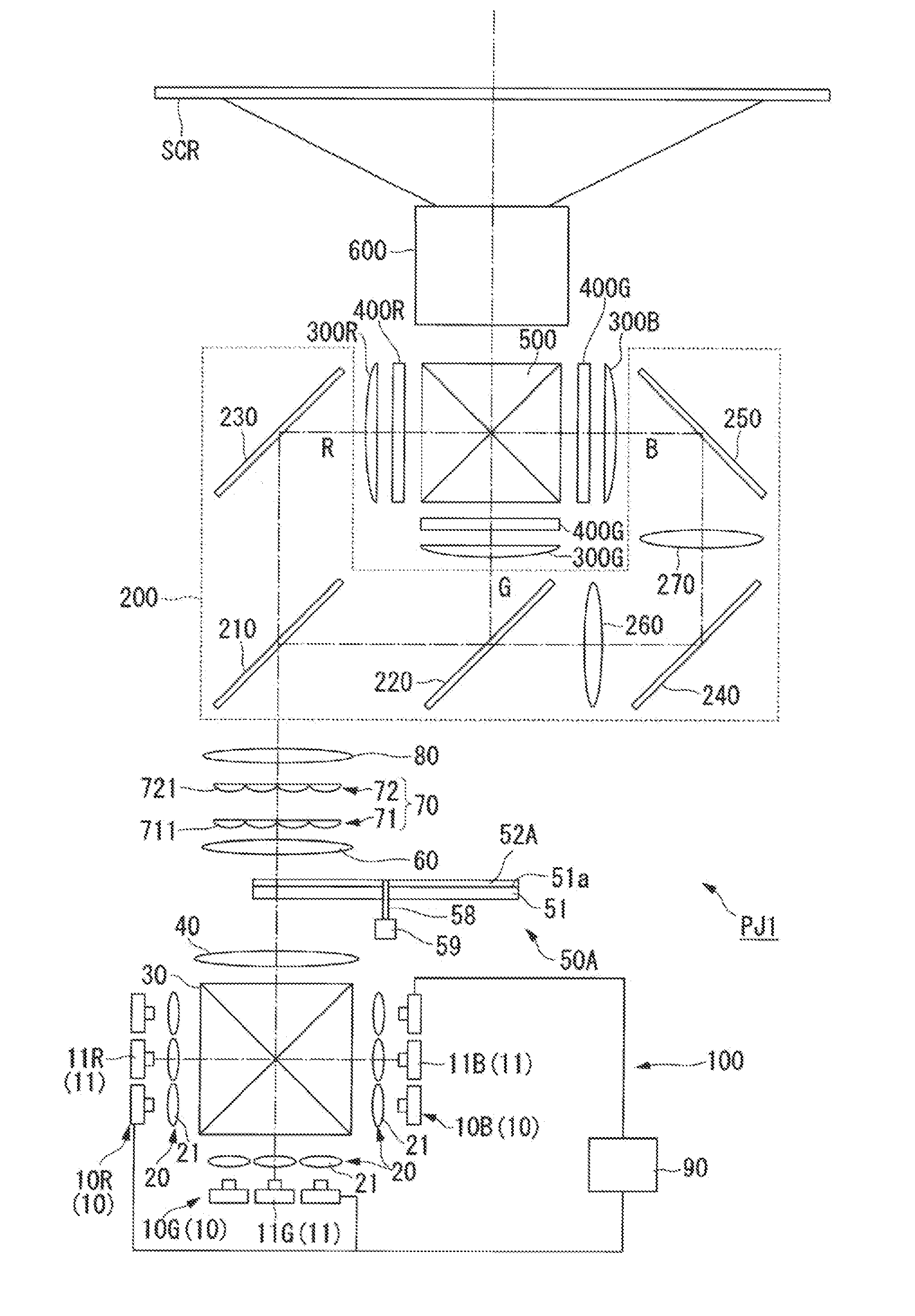
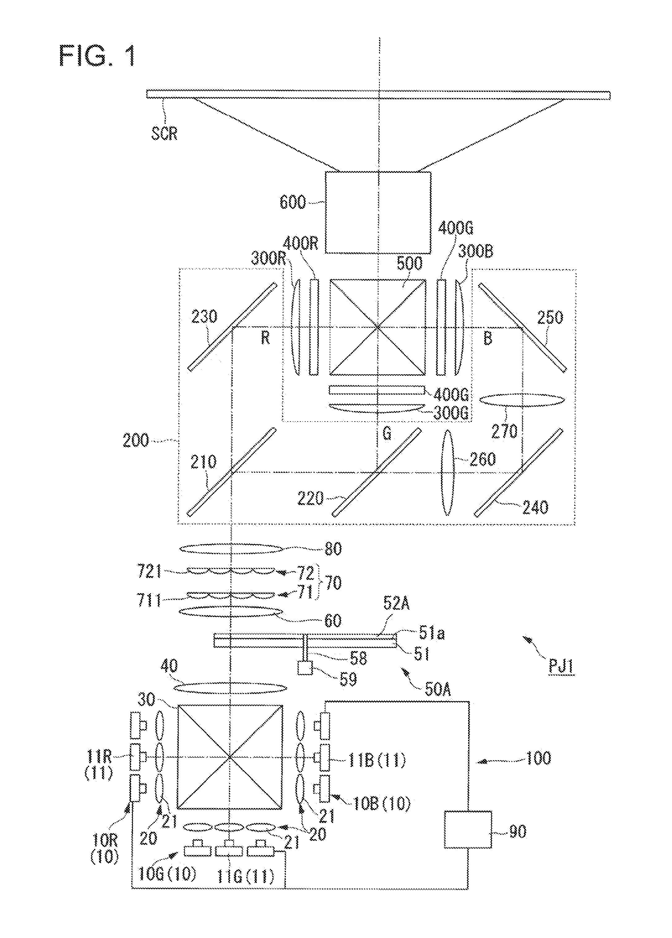
[0043]FIG. 1 is a schematic diagram illustrating a projector PJ1 according to the present embodiment. As illustrated in FIG. 1, the projector PJ1 includes a light source apparatus 100, a color split optical system 200, a liquid crystal light valve (light modulation element) 400R, a liquid crystal light valve 400G, a liquid crystal light valve 400B, a color combination element 500, and a projection optical system 600.
[0044]The projector PJ1 schematically operates as follows. Light emitted from the light source apparatus 100 is split into a plurality of color light beams by the color split optical system 200. The plurality of color light beams split by ...
second embodiment
[0092]FIGS. 6A and 6B are schematic diagrams illustrating a light diffusion element according to the second embodiment, and are schematic diagrams illustrating a configuration of the light diffusion element having a light diffusion layer using refraction of light. FIG. 6A is a diagram corresponding to FIGS. 3A and 3C described above, and FIG. 68 is a diagram corresponding to FIGS. 3B and 3D described above.
[0093]In the light diffusion element 50B illustrated in FIG. 6A, a plurality of microlenses are formed as a lens structure in the light diffusion layer 52B. In this light diffusion element 50B, a plurality of microlenses may employ various configurations such as a spherical lens, an aspherical lens, a cylindrical lens, and a free-curved surface lens as long as refraction of light on a lens surface is used.
[0094]For example, using microlenses which have different curvatures of lens surfaces between two directions perpendicular to each other, diffusion angles of the diffused light D...
third embodiment
[0097]FIGS. 7A to 7D are schematic diagrams illustrating a light diffusion element according to the third embodiment, and are schematic diagrams illustrating a configuration of the light diffusion element having a light diffusion layer using diffraction of light. FIGS. 7A to 7D are diagrams corresponding to the above-described FIGS. 3A to 3D.
[0098]A light diffusion element 50C illustrated in FIG. 7A and a light diffusion element 50D illustrated in FIG. 7C have computer generated hologram (CGH) elements which are formed as diffraction structures in a light diffusion layer 52C and a light diffusion layer 52D. The CGH element can generate not only any diffusion angle of the diffused light DL but also any distribution shape of a cross-sectional shape of the diffused light DL, and thus can generate an annular ring shape as illustrated in FIG. 7B or a parallelogram shape (square shape) as illustrated in FIG. 7D. The diffraction structure may employ various configurations as long as diffra...
PUM
 Abstract
Description
Claims
Application Information
 - R&D
- Intellectual Property
- Life Sciences
- Materials
- Tech Scout
- Unparalleled Data Quality
- Higher Quality Content
- 60% Fewer Hallucinations
Browse by: Latest US Patents, China's latest patents, Technical Efficacy Thesaurus, Application Domain, Technology Topic, Popular Technical Reports.
© 2025 PatSnap. All rights reserved.Legal|Privacy policy|Modern Slavery Act Transparency Statement|Sitemap|About US| Contact US: help@patsnap.com