Diagnostic apparatus

a technology of diagnostic equipment and cytometry, which is applied in the field of diagnostic methods and apparatus, can solve the problems of high cost, complicated procedure, and large variability, and achieves the effects of high cost, high accuracy, and high accuracy

Active Publication Date: 2014-08-21
ADVANCED ANIMAL DIAGNOSTICS
View PDF5 Cites 17 Cited by
  • Summary
  • Abstract
  • Description
  • Claims
  • Application Information

AI Technical Summary

Problems solved by technology

This is approximately 10% of the total value of farm milk sales, and about two-thirds of this loss is due to reduced milk production in subclinically infected cows.
One method for detecting the differential milk leukocyte count is using flow-cytometry, which is an expensive, sophisticated tool typically only found in top research laboratories and generally not practical for the farmer.
Another method for detecting the differential milk leukocyte count is the “manual milk differential smear” (MMDS), which is a difficult and time consuming procedure, and is subject to great variability, even when performed by highly trained laboratory technologists.
Both flow-cytometry and MMDS present practical difficulties for field research or a barn environment.
While manual and automated procedures for carrying out disease detection with the aid of such a sample cartridge are described, again there is not described a system and apparatus useful for implementing such procedures in a field or barn environment.

Method used


Image

  • Diagnostic apparatus
  • Diagnostic apparatus
  • Diagnostic apparatus

Examples


example 1

Exogenous Target-Assisted Autofocus

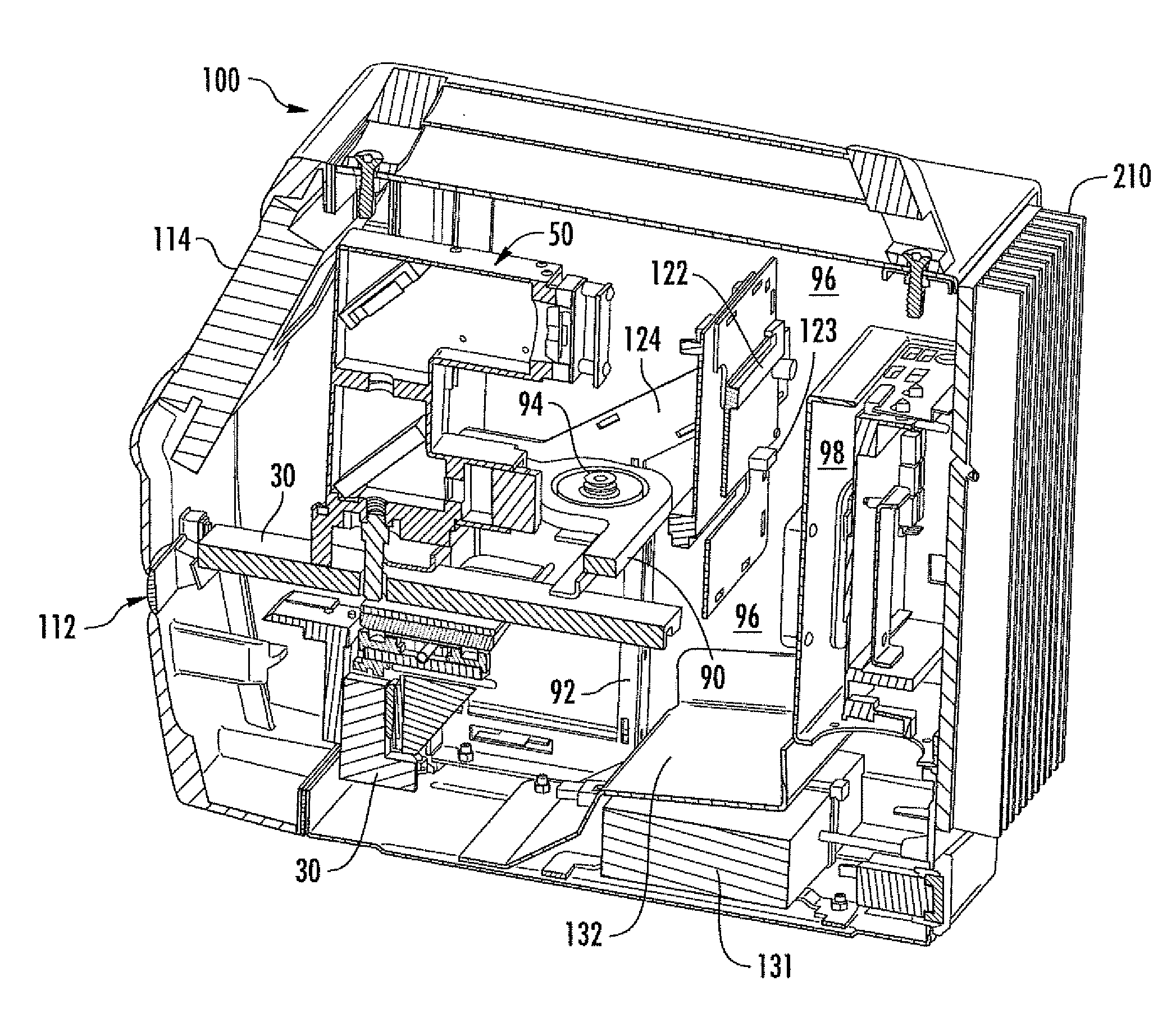
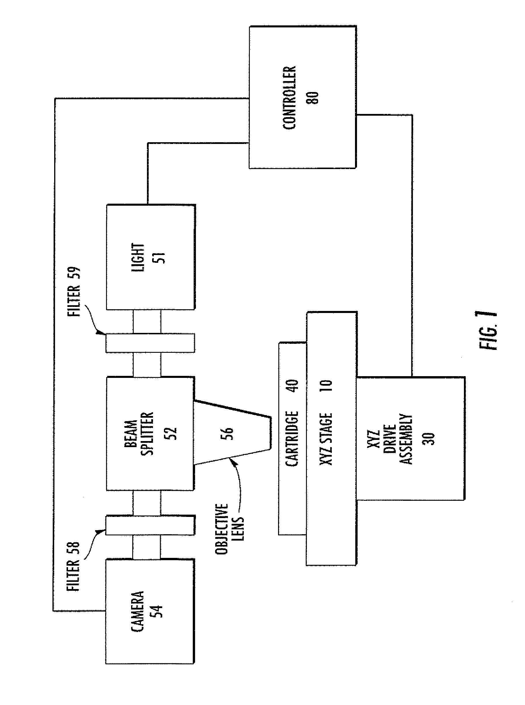
[0085]An embodiment of the invention is carried out by addition of microscopic fluorescent beads to a sample to be imaged, in combination with an automated microscope including an XYZ stage under the control of a computer. A sufficient concentration of such beads will ensure that there is a very high probability of having beads within any given field of view, thereby ensuring that there is sufficient texture for the autofocus algorithm.

[0086]In general, when an automated microscope focuses, a typical approach is a sequence as follows:[0087]1. Move to some Z location.[0088]2. Mathematically process the digital image to obtain a “score” of the image that represents, in relative terms, whether the field of view is in focus.[0089]3. Repeat steps 1 and 2 until a peak is found in the focus graph. This peak will represent the position at which that field of view is in best focus.

example 2

Sample or Surface Interpolation

[0090]By including exogeneous focal targets at a plurality of separate locations in the sample to be imaged, or on the sample carrier surface to be imaged (so long as cells / analytes to be imaged and focus particles are in the same image plane or “Z stack”), the surface or sample can be interpolated by inclusion of a suitable interpolation program, routine or subroutine within the autofocus subroutine, to thereby facilitate imaging of the sample, or speed imaging of the sample.

[0091]Such interpolation can be carried out by any suitable algorithm or method, including but not limited to the planar best fit method, the weighted least squares fit method, and the quadratic fit method. Such procedures are known and described in, for example, I. Coope, “Circle fitting by linear and nonlinear least squares”. Journal of Optimization Theory and Applications 76 (2): 381 (1993); Ake Bjorck, Numerical Methods for Least Squares Problems, Society for Industrial and Ap...


PUM

PropertyMeasurementUnit
thermal design power ratingaaaaaaaaaa
center wavelengthaaaaaaaaaa

Abstract

An automated microscope apparatus comprises an outer housing having an external wall; optionally but preferably an internal wall in the housing configured to form a first compartment and a separate second compartment in the outer housing; a microscope assembly in the housing (preferably in the first compartment); a microprocessor in the housing (preferably in the second compartment), and (optionally but preferably) a heat sink mounted on the housing external wall, preferably adjacent the second compartment, with the microprocessor thermally coupled to said heat sink and operatively associated with the microscope assembly. Systems and methods employing the same are also described, along with component parts thereof.

Description

RELATED APPLICATIONS[0001]This application claims the benefit of U.S. Provisional Patent Application Ser. No. 61 / 667,691, filed Jul. 3, 2012, and US Provisional Patent Application Ser. No. 61 / 696,517, filed Sep. 4, 2012, the disclosures of which are incorporated by reference herein in their entirety.FIELD OF THE INVENTION[0002]The present invention concerns diagnostic methods and apparatus, particularly methods and apparatus useful for detecting white blood cells or analytes in bodily fluids of production animals (for example, bovine mastitis in cattle from milk).BACKGROUND OF THE INVENTION[0003]Mastitis is the inflammation of the mammary gland caused by microorganisms that invade one or more quadrants of the bovine udder, multiply, and produce toxins that are harmful to the mammary gland. Economic loss to mastitis in the United States is estimated to be over 2 billion dollars. This is approximately 10% of the total value of farm milk sales, and about two-thirds of this loss is due ...

Claims


Application Information

Patent Timeline
Patent Type & Authority Applications(United States)
IPC IPC(8): G02B21/26G02B21/28G01N33/487
CPCG02B21/26G02B21/28G01N33/48785G02B21/0016G06F1/20
Inventor BRESOLIN, STEFANOCALDERWOOD, DAVID A.HEINECK, TOBIAS M.NEWCOMB, DAVIDPAUL, CHRISPOLLARD, JASPER N.RODRIGUEZ, RODOLFO R.YOUNG, DEMETRIS
Owner ADVANCED ANIMAL DIAGNOSTICS
Why Eureka
Try Eureka