
Exsanguination preventing device

a technology of exsanguination and device, which is applied in the direction of therapeutic cooling, gravity drainage system, other medical devices, etc., can solve the problems of insufficient arrest of blood loss of injured soldiers, inability to prevent blood loss, and death of soldiers,

Active Publication Date: 2014-08-21
ERICKSON DIRK JEROME
View PDF14 Cites 8 Cited by
  • Summary
  • Abstract
  • Description
  • Claims
  • Application Information

AI Technical Summary

Benefits of technology

The present invention is a blood recirculating system that prevents exsanguination, which can occur when an arterial laceration occurs. The device is simple and portable, allowing operators of different skill levels to use it. It slows or stops the loss of blood by closing the circuit opened by the injury and keeps the patient alive until they can be delivered to an operating room. The device can be maintained operational with different power sources and is designed to be easily positioned on a surface during field use. It also includes an oxygenating device that provides oxygen to the blood. The technical effects of this invention are the ability to prevent excessive bleeding and save potential loss of life in a portable and easy-to-use device.

Problems solved by technology

A typical cause of exsanguinations is traumatic injury where blood loss cannot be arrested.
In battlefield situations, blood loss of an injured soldier may not be arrested to a sufficient degree during combat or in field hospitals, and blood loss to a fatal amount may occur during transport to a care center.
Those systems, however, are bulky and not particularly suited for use in a battlefield, or in other emergency situations such as a fire rescue or an accident in a remote location where trained personnel or hospital equipment may not be readily available.
In those situations, application to the patient of a system in the prior art may be difficult; and air or dirt may become trapped within the system and be lethal to the patient; or blood recirculation may be defective, exposing the patient to the risk of oxygen deprivation and permanent damage.

Method used


Image

  • Exsanguination preventing device
  • Exsanguination preventing device
  • Exsanguination preventing device

Examples


Embodiment Construction

[0045]Detailed descriptions of embodiments of the invention follow. It is to be understood, however, that the present invention may be embodied in various forms. Therefore, the specific details disclosed in the present description are not to be interpreted as limiting, but rather as a representative basis for teaching one skilled in the art how to employ the present invention in different systems or manners.

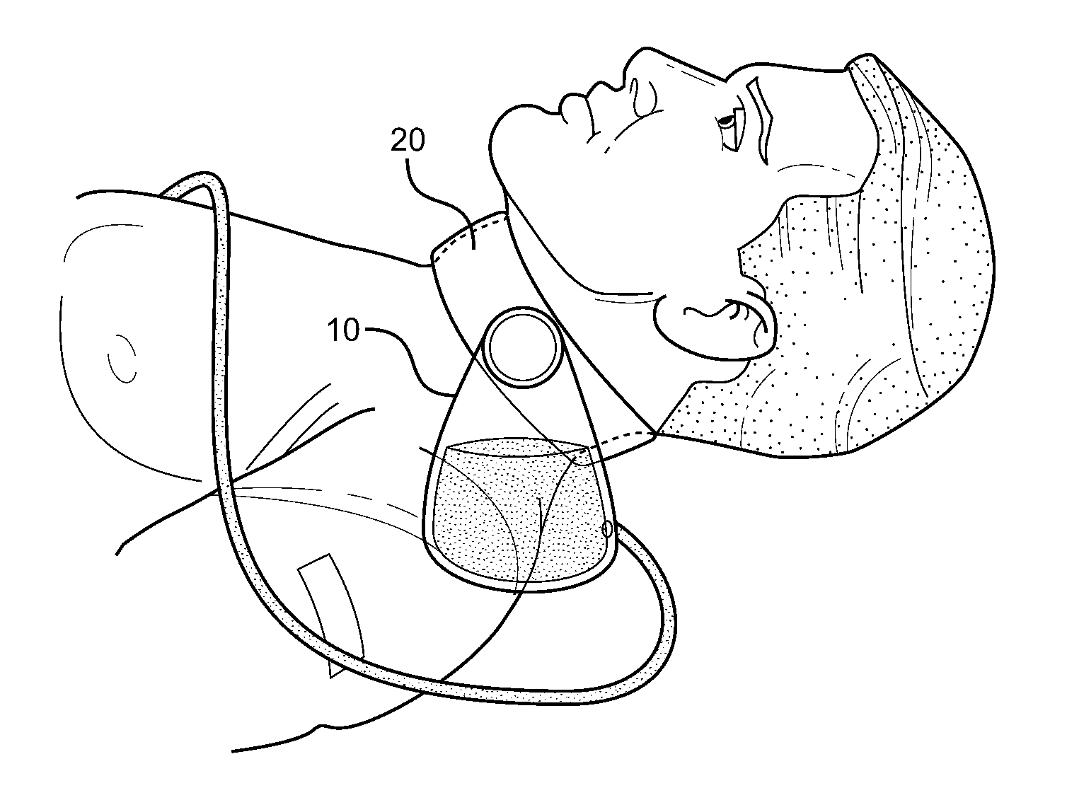
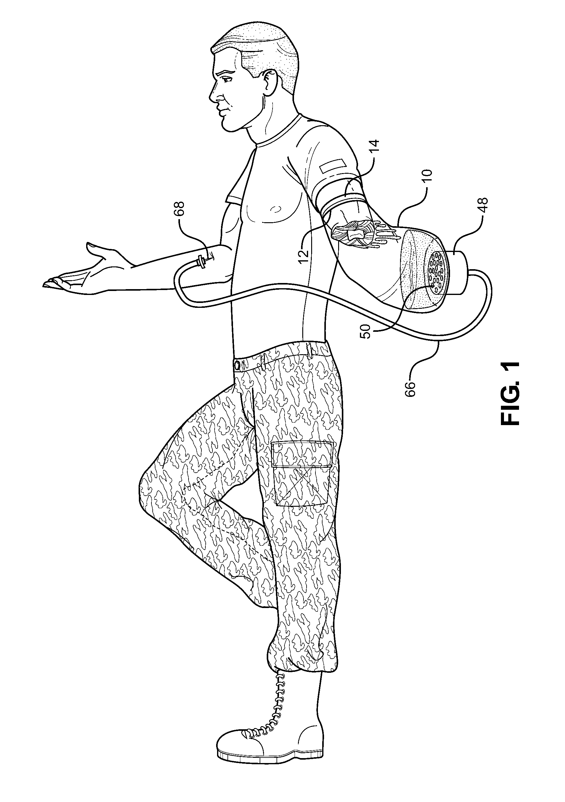
[0046]In its most basic configuration, an exsanguination preventing device according to the invention includes three major components: a collection system receiving blood from a patient; a pump, moving the blood; and a conduit, receiving the blood from the pump and delivering the whole, autologous blood back to the patient through an insertion device. Various interchangeable attachments may also be provided. All components are sized such to make the exsanguination preventing device portable in a pocket of a garment or of a backpack of a soldier.

[0047]The first major component is ...


PUM


Abstract

In one embodiment, an exsanguination preventing device includes a collection container having an inlet configured to receive blood from a patient and an outlet configured to discharge the blood; a pump operatively coupled to the collection container; a conduit fluidly coupled to the collection container, which receives the blood from the collection container, the blood being moved by the pump; and an insertion device, which delivers the blood from the conduit to a bodily part of the patient. The collection container is configured to be sealingly coupled to a wound on the patient and air entrapped within the exsanguination preventing device is removed by an air removal system, such to prevent unwanted discharge of air into the bodily part of the patient. All the components of the exsanguination preventing device are sized such to make it portable in a pocket of a garment or backpack of a soldier.

Description

FIELD OF THE INVENTION[0001]The present invention relates to a device that prevents exsanguination. More particularly, the present invention relates to a device that prevents exsanguination of a patient by recirculating autologous blood into the body of the patient.BACKGROUND OF THE INVENTION[0002]Exsanguination (colloquially known as bleeding out) is the fatal process of blood loss to an amount that causes death.[0003]A typical cause of exsanguinations is traumatic injury where blood loss cannot be arrested. For example, exsanguination is the leading cause of death on a battlefield. Non-battlefield causes can include murder by shooting or stabbing; motor vehicle accidents; suicide by cutting arteries; and partial or complete amputation of limbs due to workplace accidents.[0004]A victim does not have to lose all of his (her) blood to cause death. Depending upon the age, health, and fitness level of the individual, a victim may die from losing half or two-thirds of their blood. In ba...

Claims


Application Information

Patent Timeline
Patent Type & Authority Applications(United States)
IPC IPC(8): A61M1/36A61M1/16
CPCA61M1/3653A61M1/168A61M2205/364A61M1/3627A61M1/1629A61M1/3666A61M1/3681A61M2205/3592A61M2205/502A61M2205/8206A61M1/3673A61M2205/053A61M1/1686A61M1/1688A61M1/3659A61M1/631A61M1/70A61M1/3623
Inventor ERICKSON, DIRK JEROME
Owner ERICKSON DIRK JEROME
Learn More