Control system for a decanter centrifuge

a control system and centrifuge technology, applied in centrifuges, separation processes, instruments, etc., can solve the problems of not allowing the feed pump to operate, requiring a great deal of effort to “unplug”, and the method of operation is very problematic and inefficient, so as to achieve the effect of easy retrofi

Inactive Publication Date: 2014-08-21
ENGIP LLC
View PDF10 Cites 5 Cited by
  • Summary
  • Abstract
  • Description
  • Claims
  • Application Information

AI Technical Summary

Benefits of technology

[0008]The instant invention is based on thin film piezoresistive material preconfigured for sensor wire attachment. This preconfigured piezoresistive cell is precisely overmolded, utilizing a durometer polyurethane elastomer for example, into a configuration that is very similar to the typical torque rest level pad. This configuration allows the load sensor to easily be retrofitted into the torque rest level. The sensor provides a directly proportional voltage indication of the planetary gearbox load which can be utilized to control the feed pump or a diverter valve. The sensor will include controller circuitry which allows the operator to set a desired maximum load as well as a dead band of normal operation. If the centrifuge load exceeds the maximum load set point, the controller will begin to reduce the feed rate until the load falls within the dead band. If the load again increases to exceed the maximum load set point, the controller will reduce the feed rate further until the load falls within the dead band. If the load decreases to a level below the dead band the controller will increase the feed rate until the load falls within the dead band.

Problems solved by technology

This arrangement will not allow the feed pump to operate unless the centrifuge is operating normally.
This method of operation is very problematic and inefficient.
If the centrifuge does trip on overload it will be “plugged” and will require a great deal of effort to “unplug.” There will be down time associated with this event and loss of revenue.
These devices are intended to protect the centrifuge from “plugging” by shutting off the feed pump, but do not control or adjust the feed rate to allow the centrifuge to continue processing.
Additionally, these systems utilize expensive load cells and the centrifuge over torque device must be modified to accept the load cell.

Method used


Image

  • Control system for a decanter centrifuge
  • Control system for a decanter centrifuge
  • Control system for a decanter centrifuge

Examples


Embodiment Construction

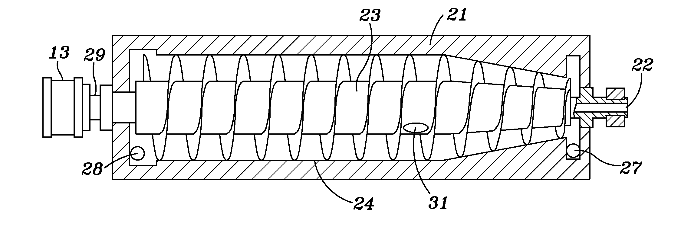
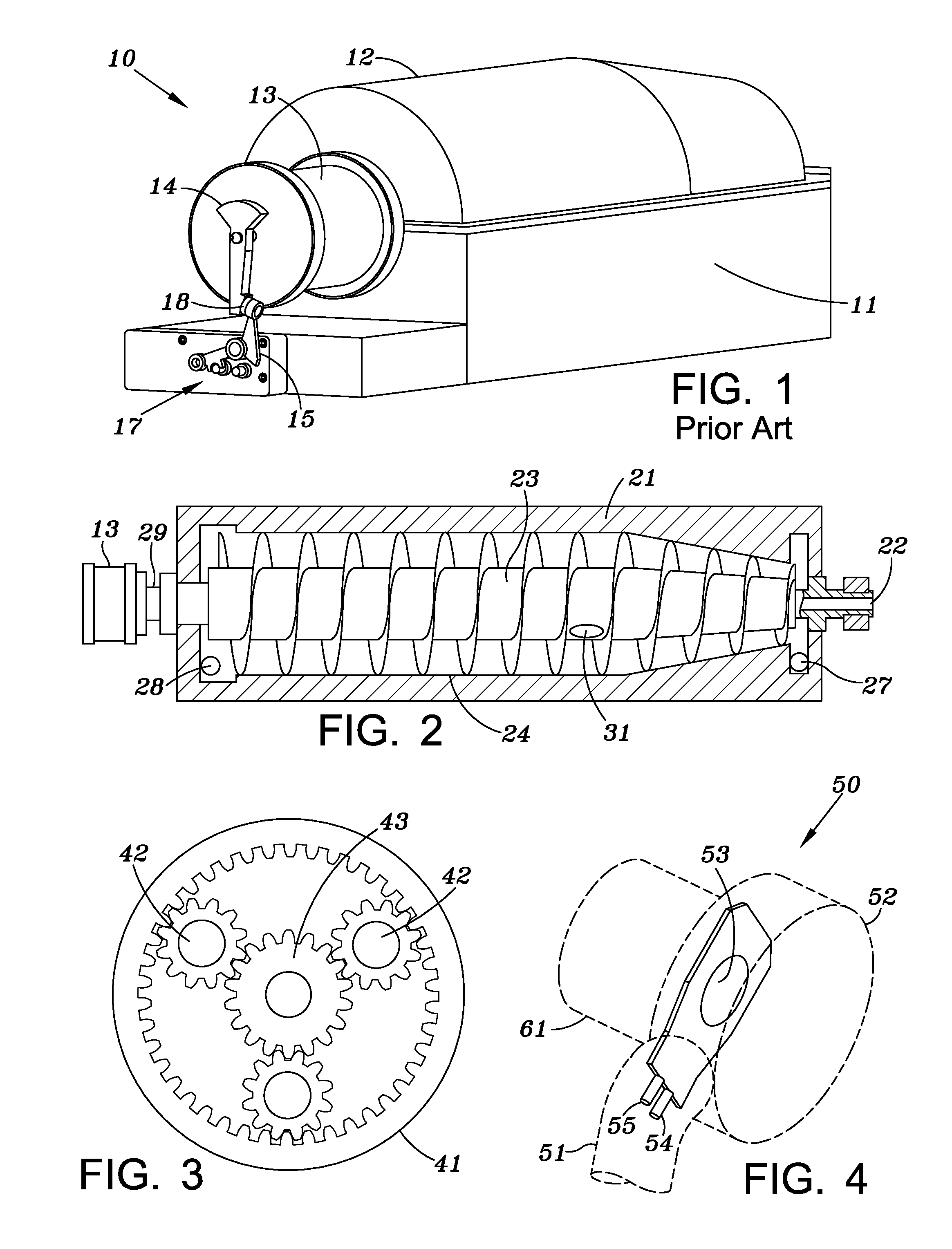
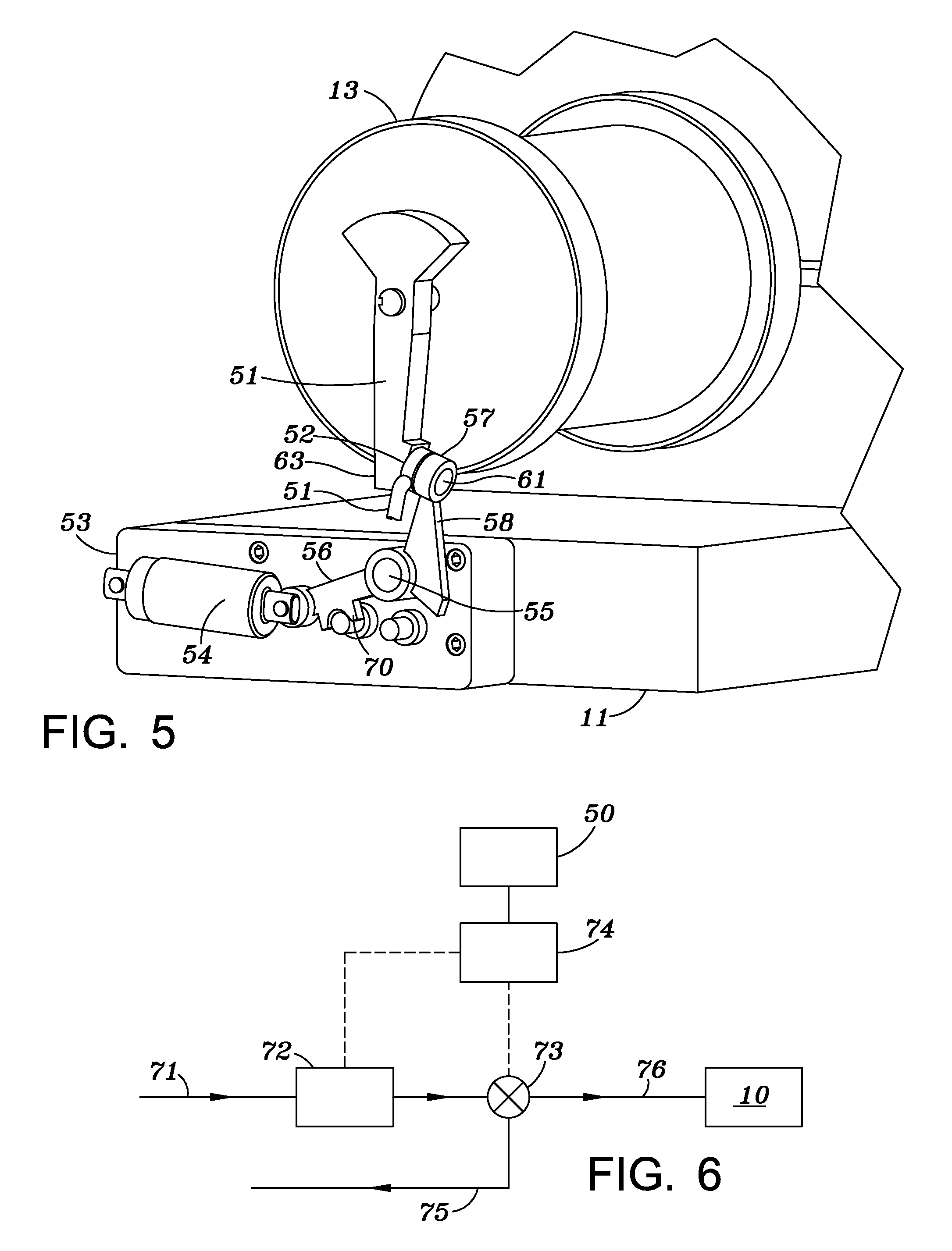
[0015]As shown in FIG. 1, a typical prior art decanter centrifuge 10 includes a base support 11 and cover 12 pivoted to the base support. A planetary gearbox housing 13 houses a planetary gear system for example as shown in FIG. 3. A torque sensing assembly 17 is connected to the base and includes a spring loaded over center assembly 54 as discussed below and a lever arm 15 pivotally connected to the over center assembly 54 and pivoted about a support pin 55 shown in FIG. 5.

[0016]Lever arm 15 includes a rest pad 18 which is adapted to be engaged by a torque sensor arm 14 which is attached to the fixed center pinion of the planetary gear system. As discussed above, when the torque on the fixed center pinion of the drive planetary gearing exceeds a predetermined maximum, the distal portion of the torque sensor arm 14 will exert a force on lever arm 15 sufficient to cause the over center mechanism to trip. At this point lever arm 15 will rotate downwardly as seen in FIG. 5 which allow ...


PUM

PropertyMeasurementUnit
torqueaaaaaaaaaa
cross-sectional areaaaaaaaaaaa
flexibleaaaaaaaaaa

Abstract

A torque sensing device capable of measuring the force exerted by a torque arm on a lever is positioned between the torque arm and the lever. The torque arm is connected to the pinion of a planetary gearbox for rotating the bowl and screw conveyer of a decanter centrifuge at different speeds. The torque sensing device measures the torque between the pinion gear and the planetary gearbox. The sensor can be connected to a controller which can reduce the flow of the liquid/solid mixture to the decanter centrifuge thereby/reducing the torque and avoiding substantial damage to the planetary gearbox.

Description

BACKGROUND OF INVENTION[0001]1. Field of the Invention[0002]The invention disclosed and claimed in this application is directed to a torque sensing and control system for a decanter centrifuge. A torque sensor may be incorporated into a known torque control mechanism that will measure the torque acting on a pinion gear of a planetary gearbox used to rotate the centrifuge conveyor and bowl. This data may be used to control various parameters such as the feed rate of the liquid to the separator and vary the speeds of the drive motor for the centrifuge.[0003]2. Description of Related Art[0004]Decanter centrifuges are used in a wide variety of industries to remove fine solids from liquids. In operation, the bowl spins at a high rate of speed creating centripetal force, commonly referred to as G Force, causing the heavier solids to settle to the wall of the bowl. The solids that settle to the wall are conveyed to the solids discharge end of the decanter by the screw conveyor. The screw c...

Claims


Application Information

Patent Timeline
Patent Type & Authority Applications(United States)
IPC IPC(8): B04B11/04
CPCB04B11/04B04B1/20B04B2001/2025G01L3/1478B04B1/2016B04B9/10
Inventor HILPERT, JEFFREY L.
Owner ENGIP LLC
Why Eureka
Try Eureka