Catheter

a catheter and catheter technology, applied in the field of catheters, can solve the problems of cracking or peeling of the outer layer, and achieve the effects of increasing the pitch, preventing peeling, and uniform curving of the catheter

Inactive Publication Date: 2014-08-21
ASAHI INTECC CO LTD
View PDF0 Cites 7 Cited by
  • Summary
  • Abstract
  • Description
  • Claims
  • Application Information

AI Technical Summary

Benefits of technology

[0009]Accordingly, in view of the above-described situation, it is an object of at least some embodiments of the present invention to provide a catheter that can prevent cracking or peeling of outer layers by suppressing stress that is generated at a boundary between the outer layers having different hardnesses (for example, a boundary between a body of a catheter shaft and an adjacent portion that is adjacent to the body) even if the catheter inserted in a blood vessel is placed in a curved state for a long time.
[0012]In the catheter according to some aspects of the invention, the intermediate layer has an uneven contour, and the thickness of the intermediate layer at the gap of the braid is constant. Therefore, the adhesive strength (adhesiveness) between the inner layer and the intermediate layer that covers the braid becomes uniform; and, when the catheter is curved, the movements of the braid (that is, the increasing of the pitch between portions of the braid 260) caused by the curving of the catheter can be uniformly suppressed. In addition, even if, when the catheter is curved, tensile stress towards the proximal end acts upon the first outer layer at the first portion and tensile stress towards the distal end acts upon the second outer layer at the adjacent second portion, the first and second outer layers are caught by the uneven contour of the intermediate layer by an anchor effect. Thus it is possible to prevent peeling of the first and second outer layers from the inner layer. Therefore, even if the catheter is placed in a curved state for a long time, it is possible to reduce the possibility of cracking at the boundary between the adjacent first and second portions and the possibility of peeling of the outer layers.

Problems solved by technology

However, when a catheter is inserted into a meandering blood vessel and is placed in a curved state for a long time, stress is concentrated at a boundary between the outer layers having different rigidities (that is, the boundary between the body and the distal end portion of the catheter shaft).
As a result, the outer layers may crack or peel.

Method used


Image

  • Catheter
  • Catheter
  • Catheter

Examples


Embodiment Construction

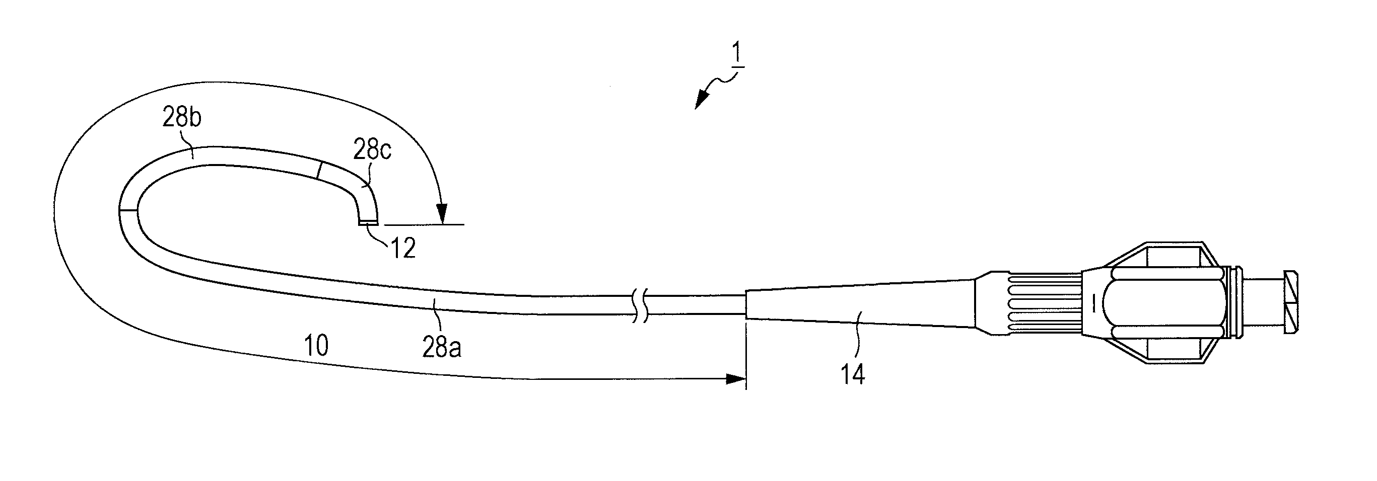
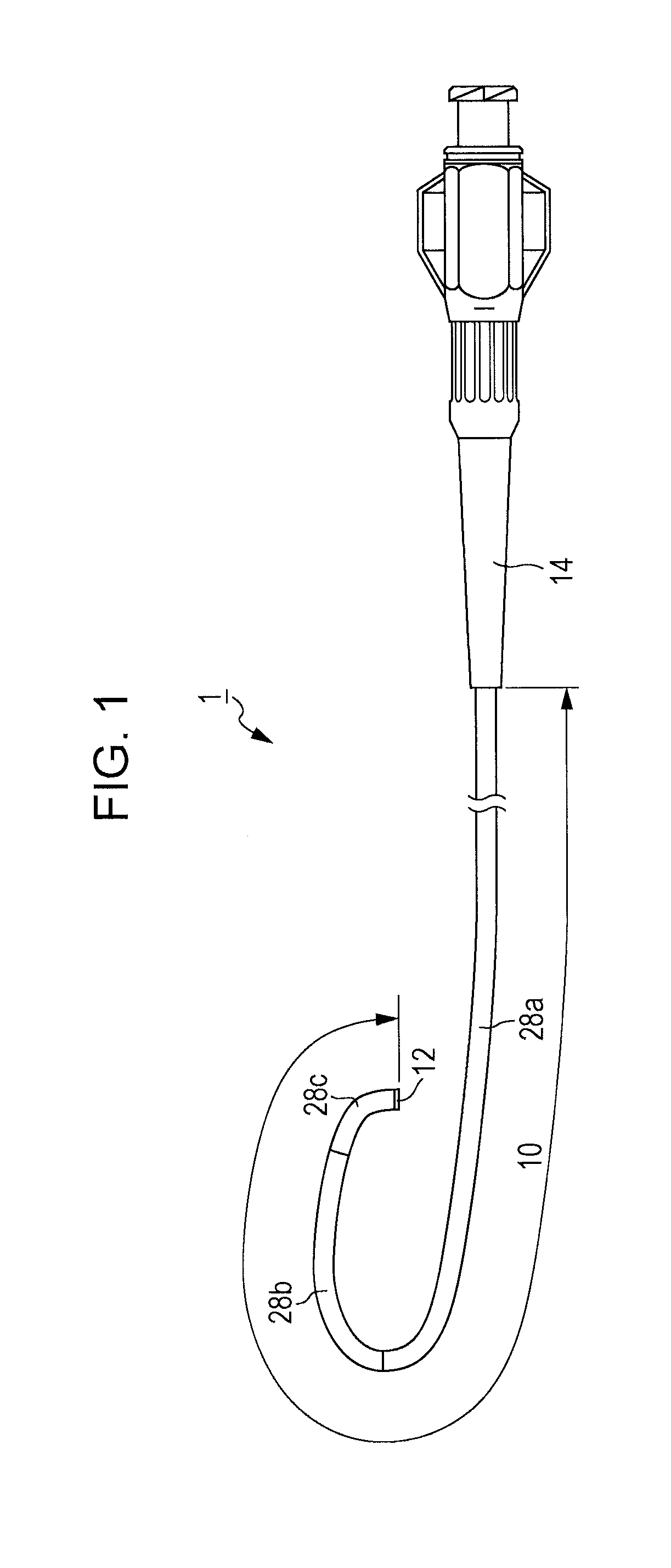
[0021]With reference to FIGS. 1 to 7, catheters 1 according to embodiments are described. In FIGS. 1 to 3 and FIGS. 6 and 7, the illustrated left side corresponds to a distal end that is inserted into a human body and the illustrated right side corresponds to a proximal end (base end) that is operated by an operator such as a doctor.

[0022]The catheter 1 shown in FIG. 1 is a tubular medical device whose overall length is approximately 1200 mm. The catheter 1 primarily includes a flexible catheter shaft 10, a distal-end tip 12 bonded to a distal end of the catheter shaft 10, and a connector 14 secured to a proximal end portion of the catheter shaft 10.

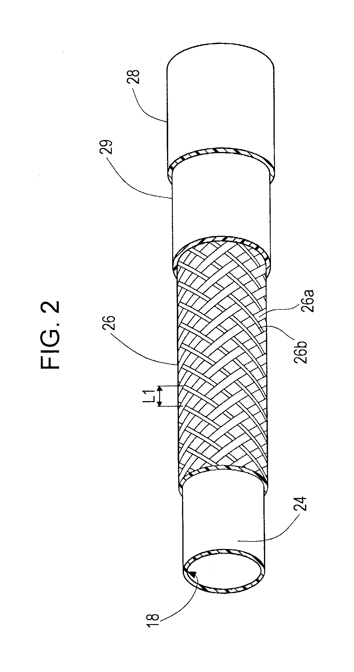
[0023]As shown in FIGS. 2 and 3, the catheter shaft 10 includes, from an inner side of the catheter shaft 10 in a radial direction, an inner layer 24, a braid 26 (serving as a reinforcing member), an intermediate layer 29, and an outer layer 28.

[0024]The inner layer 24 is formed of a resin and forms a lumen in an inner portion thereof fo...


PUM

PropertyMeasurementUnit
shore hardnessaaaaaaaaaa
lengthaaaaaaaaaa

Abstract

A catheter has an intermediate layer with a constant thickness in first and second adjacent portion, and the adhesive strength between the intermediate layer and an inner layer is uniform. When the catheter is curved, the movement of a braid caused by the curving of the catheter can be uniformly suppressed within the adjacent first and second portions. Even if, when the catheter is curved, a tensile stress towards a proximal end acts upon a first outer layer at the first portion and a tensile stress towards a distal end acts upon a second outer layer at the adjacent second portion, the first and second outer layers are caught by an uneven contour of the intermediate layer by an anchor effect, so that it is possible to prevent peeling of the first and second outer layers from the intermediate layer.

Description

CROSS-REFERENCE TO RELATED APPLICATION[0001]The present application claims priority to Japanese Patent Application No. 2013-028088 filed in the Japan Patent Office on Feb. 15, 2013, the entire contents of which are incorporated herein by reference.BACKGROUND OF THE INVENTION[0002]The disclosed embodiments relate to a medical device. Specifically, the disclosed embodiments relate to a catheter that is inserted into a blood vessel, and, particularly, to a catheter including outer layers having different rigidities.[0003]A catheter that is inserted into a blood vessel is a long and narrow medical device having a flexible structure. A catheter is used as an examining device that diagnoses a disease (such as identifying the location of a stenosis that requires treatment or determining the degree of development of the stenosis), or as a treating device that treats a disease (such as treating a stenosis or injecting a medicine into the stenosis).[0004]In general, an examining catheter and ...

Claims


Application Information

Patent Timeline
Patent Type & Authority Applications(United States)
IPC IPC(8): A61M25/00
CPCA61M25/0053A61M25/0045A61M25/005A61M2025/0059
Inventor MIYATA, NAOHIKOOSHIMA, FUMIYOSHI
Owner ASAHI INTECC CO LTD
Why Eureka
Try Eureka