Vision-Based Aircraft Landing Aid

Inactive Publication Date: 2014-08-21
CHENGDU HAICUN IP TECH +1
View PDF5 Cites 8 Cited by
  • Summary
  • Abstract
  • Description
  • Claims
  • Application Information

AI Technical Summary

Benefits of technology

[0007]It is a principle object of the present invention to provide a low-cost landing aid.
[0008]It is a further object of the present invention to help student pilots to learn landing.
[0009]In accordance with these and other objects of the present invention, a vision-based aircraft landing aid is disclosed.
[0010]The present invention discloses a vision-based aircraft landing aid. It comprises a camera and a processor. The camera is mounted in the aircraft forward-facing and acquires a sequence of raw runway images. The processor processes a raw runway image to extract its roll angle γ. After obtaining γ, the raw runway image is corrected by rotating about its principal point by −γ in such a way that the rotated (i.e. γ-corrected) runway image has a horizontal horizon. Further image processing will be carried out on the rotated runway image. Hereinafter, a horizontal line passing the principal point of the rotated runway image is referred to as the principal horizontal line H and a vertical line passing the principal point is referred to as the principal vertical line V. The intersection of the left and right extended runway edges is denoted by P and its coordinate XP (i.e. the distance between the intersection P and the principal horizontal line H) is used to calculate the pitch angle ρ, i.e. ρ=atan(Xp/f), while its coordinate YP (i.e. the distance between the intersection P and the principal vertical line V) is used to calculate the yaw angle α, i.e. α=atan[(YP/f)*cos(ρ)], where f is the focal length of the camera.

Problems solved by technology

Landing is the most challenging part of flying.
Student pilots generally have difficulty judging the flare altitude and need to practice hundreds of landings before getting to know when to flare.
Practicing such a large number of landings lengthens the training time, wastes a large amount of fuel

Method used


Image

  • Vision-Based Aircraft Landing Aid
  • Vision-Based Aircraft Landing Aid
  • Vision-Based Aircraft Landing Aid

Examples


Example

[0022]It should be noted that all the drawings are schematic and not drawn to scale. Relative dimensions and proportions of parts of the device structures in the figures have been shown exaggerated or reduced in size for the sake of clarity and convenience in the drawings. The same reference symbols are generally used to refer to corresponding or similar features in the different embodiments.

DETAILED DESCRIPTION OF THE PREFERRED EMBODIMENTS

[0023]Those of ordinary skills in the art will realize that the following description of the present invention is illustrative only and is not intended to be in any way limiting. Other embodiments of the invention will readily suggest themselves to such skilled persons from an examination of the within disclosure.

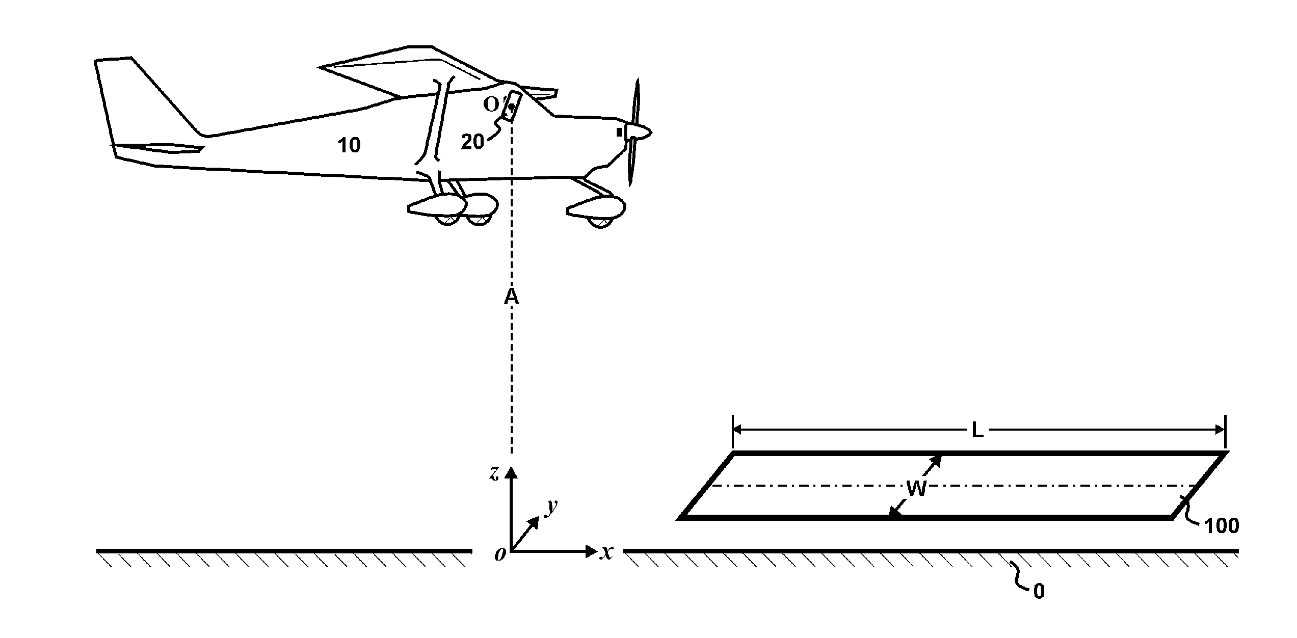
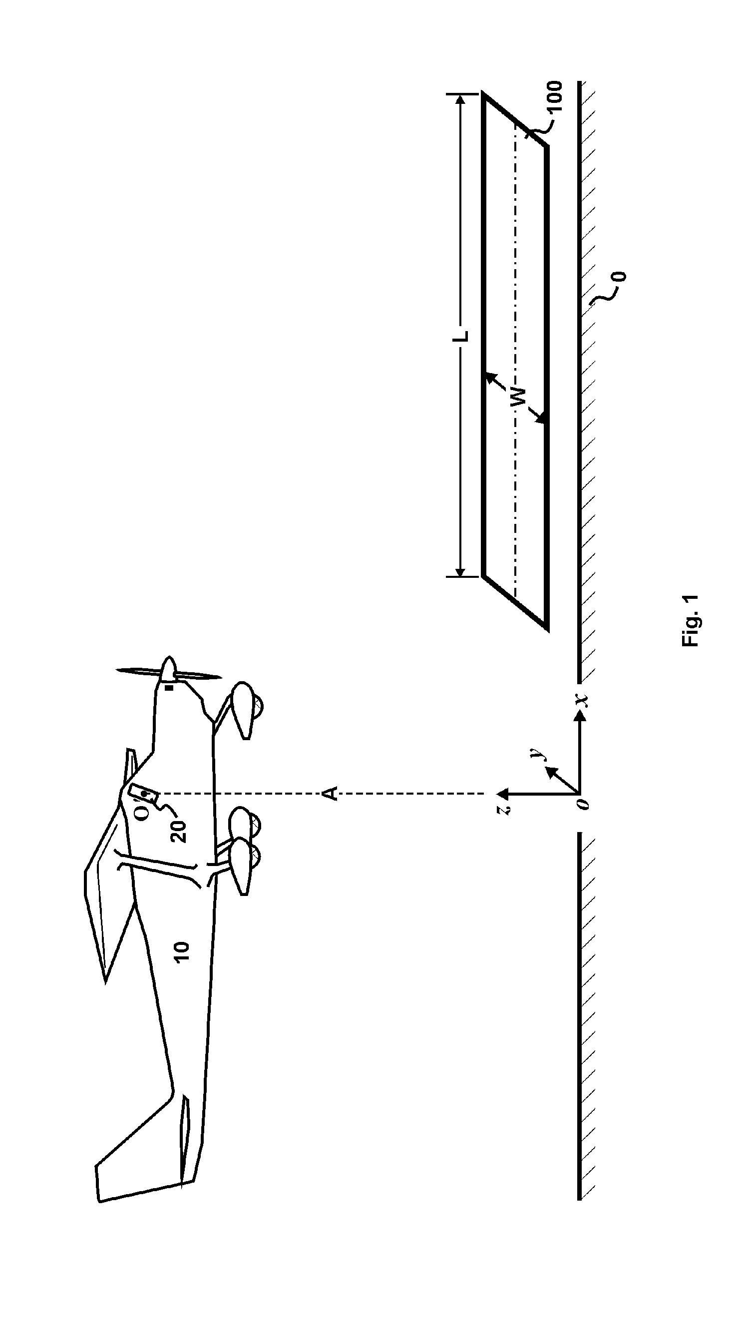
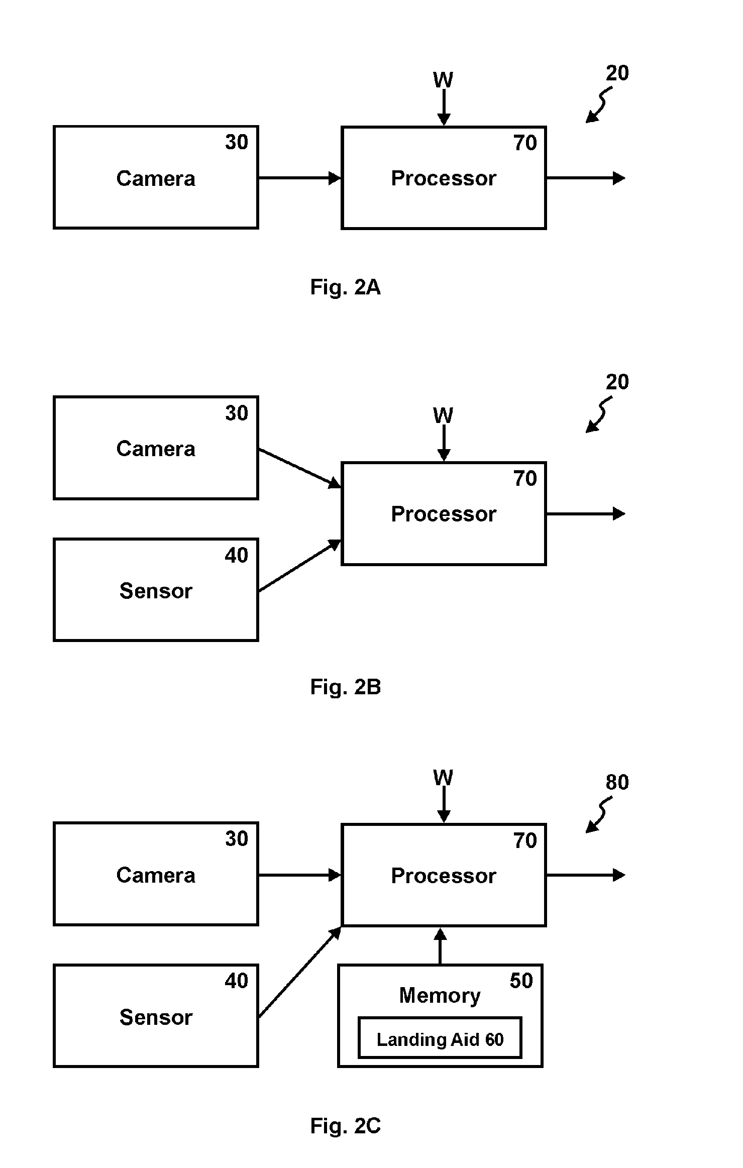
[0024]Referring now to FIG. 1, an aircraft 10 with a preferred vision-based landing aid 20 is disclosed. The vision-based landing aid 20 is mounted behind the wind-shield of the aircraft 10 and faces forward. It could be a camera, a compu...


PUM


Abstract

The present invention discloses a vision-based aircraft landing aid. During landing, it acquires a sequence of raw runway images. The raw runway image is first corrected for the roll angle (γ). The altitude (A) can be calculated based on the runway width (W) and the properties related to both extended runway edges on the rotated (γ-rotated) runway images. Smart-phone is most suitable for vision-based landing aid.

Description

CROSS-REFERENCE TO RELATED APPLICATIONS[0001]This application claims priority of a provisional application entitled “Vision-Based Aircraft Landing Aid”, Ser. No. 61 / 767,792, filed Feb. 21, 2013.BACKGROUND[0002]1. Technical Field of the Invention[0003]The present invention relates to an aircraft landing aid, more particularly to a landing aid based on computer vision.[0004]2. Prior Arts[0005]Landing is the most challenging part of flying. When an aircraft flies into the ground effect, a pilot initiates a pitch change so that the descent rate of the aircraft can be reduced. This pitch change is referred to as flare, and the time and altitude to initiate flare are referred to as flare time and flare altitude, respectively. For small aircrafts, the flare altitude is typically ˜5 m to ˜10 m above ground level (AGL). Student pilots generally have difficulty judging the flare altitude and need to practice hundreds of landings before getting to know when to flare. Practicing such a large nu...

Claims


Application Information

Patent Timeline
IPC IPC(8): G08G5/02G01C5/00
CPCG01C5/005G08G5/02G08G5/025G06T7/70B64D45/08H04N7/185G06T2207/10016G06T2207/30252
Inventor ZHANG, GUOBIAO
Owner CHENGDU HAICUN IP TECH
Why Eureka
Try Eureka