Mixed air removal device and power generator including the same

a technology of air removal device and power generator, which is applied in the direction of water feed control, lighting and heating apparatus, separation processes, etc., can solve the problems of reduced efficiency, difficulty in condensing medium in condenser, and difficulty in vaporizing medium, so as to increase the pressure of the pressure container and reduce the amount of organic gas discharged to the outside of the device.

Active Publication Date: 2014-08-28
FUJI ELECTRIC CO LTD
View PDF6 Cites 3 Cited by
  • Summary
  • Abstract
  • Description
  • Claims
  • Application Information

AI Technical Summary

Benefits of technology

[0054]According to the present invention, a mixture gas is compressed in a pressure container, and the compressed gas is supplied to a membrane unit via a pressure-reducing regulator valve, thus making it possible to increase a pressure of the pressure container irrespective of an allowable pressure value for the membrane unit, and to increase an amount of an organic gas condensed in the pressure container. As a result, an amount of the organic gas discharged to outside of a device can be reduced.

Problems solved by technology

In general, when a medium having a high vapor pressure (i.e., a low boiling point) is used, the medium is easily vaporized in an evaporator but has difficulty in being condensed in a condenser.
To the contrary, when a medium having a low vapor pressure (i.e., a high boiling point) is used, the medium has difficulty in being vaporized but is easily condensed.
Such air intrusion increases a turbine outlet pressure, resulting in a reduction in efficiency.

Method used


Image

  • Mixed air removal device and power generator including the same
  • Mixed air removal device and power generator including the same
  • Mixed air removal device and power generator including the same

Examples


Embodiment Construction

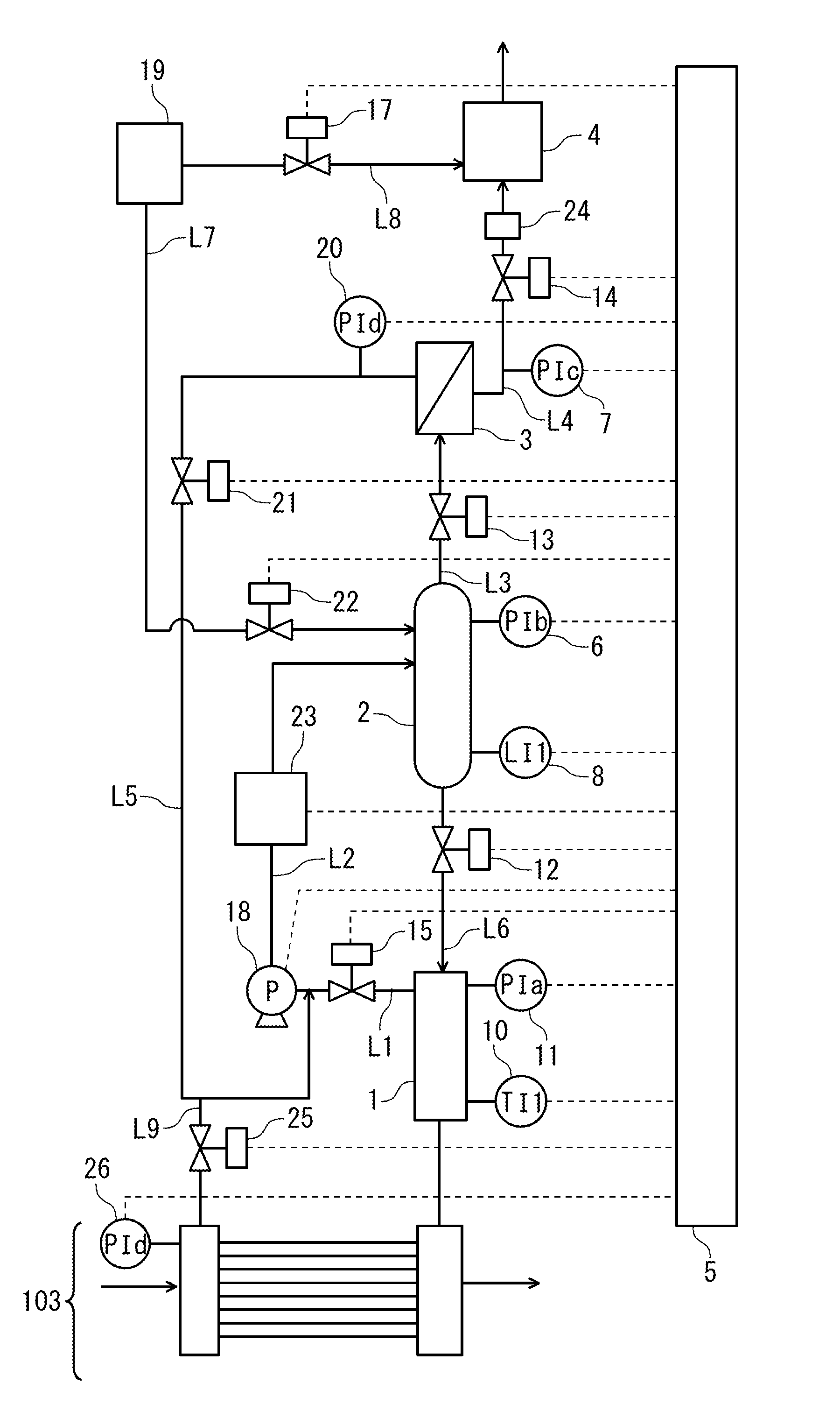
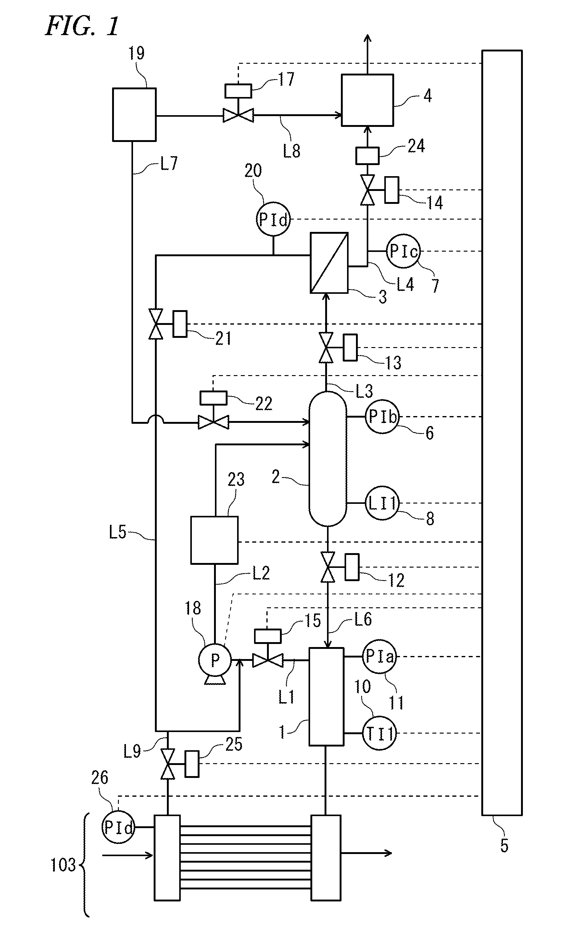
[0059]Hereinafter, an embodiment of the present invention will be described with reference to the drawings. FIG. 1 is a diagram illustrating a configuration of a mixed air removal device according to the embodiment of the present invention.

[0060]A second condenser 103 in FIG. 1 corresponds to a second condenser 103 in FIG. 4. A reservoir 1 is connected to an upper portion of an outlet side collector of the second condenser 103, and is equipped with: a thermometer 10 that measures a temperature of the reservoir 1; and a pressure gauge 11 that measures a pressure of the reservoir 1. An upper portion of the reservoir 1 and an inlet of a pump 18 are connected to each other through piping L1. The pump 18 and a pressure container 2 are connected to each other through piping L2. A first condenser 23 is provided somewhere along the piping L2. The first condenser 23 is not an essential component, but it is preferable that the first condenser 23 be provided in order to promote condensation of...


PUM


Abstract

A device for automatically detecting and removing air from a gas mixture of an organic gas and air includes calculating a saturation pressure value based on a temperature of the gas mixture in a reservoir 1, and obtaining a pressure threshold value by adding a margin value to the saturation pressure value. When the pressure value inside the reservoir 1 is higher than the pressure threshold value, air is detected to be in the gas mixture. After this detection, a controller 5 pressurizes and introduces the gas mixture into a pressure container 2 to condense the organic gas in the gas mixture, thus producing a diluted gas mixture. Subsequently, the diluted gas mixture is introduced to a supply side of a membrane unit 3, the organic gas in the diluted gas mixture is recovered at a permeation side thereof, and a residual gas is discharged outside of the device.

Description

TECHNICAL FIELD[0001]The present invention relates to a device for removing air mixed into an organic gas.BACKGROUND ART[0002]Nowadays, as an energy recovery apparatus, attention is particularly being directed to a power generator that uses a low-boiling-point medium for generating power by recovering thermal energy from a low temperature heat source which has not been utilized for conventional geothermal power generation that uses a steam turbine (see Patent Document 1).[0003]FIG. 4 illustrates a basic system diagram of a conventional power generator that uses a low-boiling-point medium. In this power generator, heat is exchanged between a medium having a boiling point lower than that of water and a heat source through an evaporator 100 to evaporate the medium and rotate a turbine 101 by vapors from the medium, so that the resulting rotational force activates a generator 102 to obtain electric power. The medium discharged from the turbine is condensed in a second condenser 103, pas...

Claims


Application Information

Patent Timeline
Patent Type & Authority Applications(United States)
IPC IPC(8): B01D53/22F01K19/00F01K9/00F25J3/06F01K25/08
CPCB01D53/229F25J3/0605F01K25/08F01K9/003F01K19/00B01D2053/221B01D53/22F01K9/00
Inventor HATAMA, MIKIKOKUBOTA, KOKANKAWAHARA, YOSHITAKASGU, HIROAKIMYOGAN, ICHIROOSAWA, ISAMU
Owner FUJI ELECTRIC CO LTD
Why Eureka
Try Eureka