Air intake system for internal combustion engine

Active Publication Date: 2014-08-28
MAHLE JAPAN LTD
View PDF0 Cites 22 Cited by
  • Summary
  • Abstract
  • Description
  • Claims
  • Application Information

AI Technical Summary

Benefits of technology

[0019]With this structure as well, as same as the case where the valve accommodating recess and the intake port are directly connected through the communication passage, by a suction force by a negative pressure of the internal combustion engine from the intake port, the deposits in the valve accommodating recess is sucked into the intake port through the penetration hole and the air intake passage, and the deposition (accumulation) of the deposits in the valve accommodating recess can be suppressed.
[0020]According to the present invention, since the deposition (accumulation) of the deposits in the valve accommodating recess can be suppressed, it is possible to prevent fixation or sticking of the valve body which is cau

Problems solved by technology

This deposition causes fixation or sticking of the valve body

Method used


Image

  • Air intake system for internal combustion engine
  • Air intake system for internal combustion engine
  • Air intake system for internal combustion engine

Examples


first embodiment

[0046][First Embodiment]

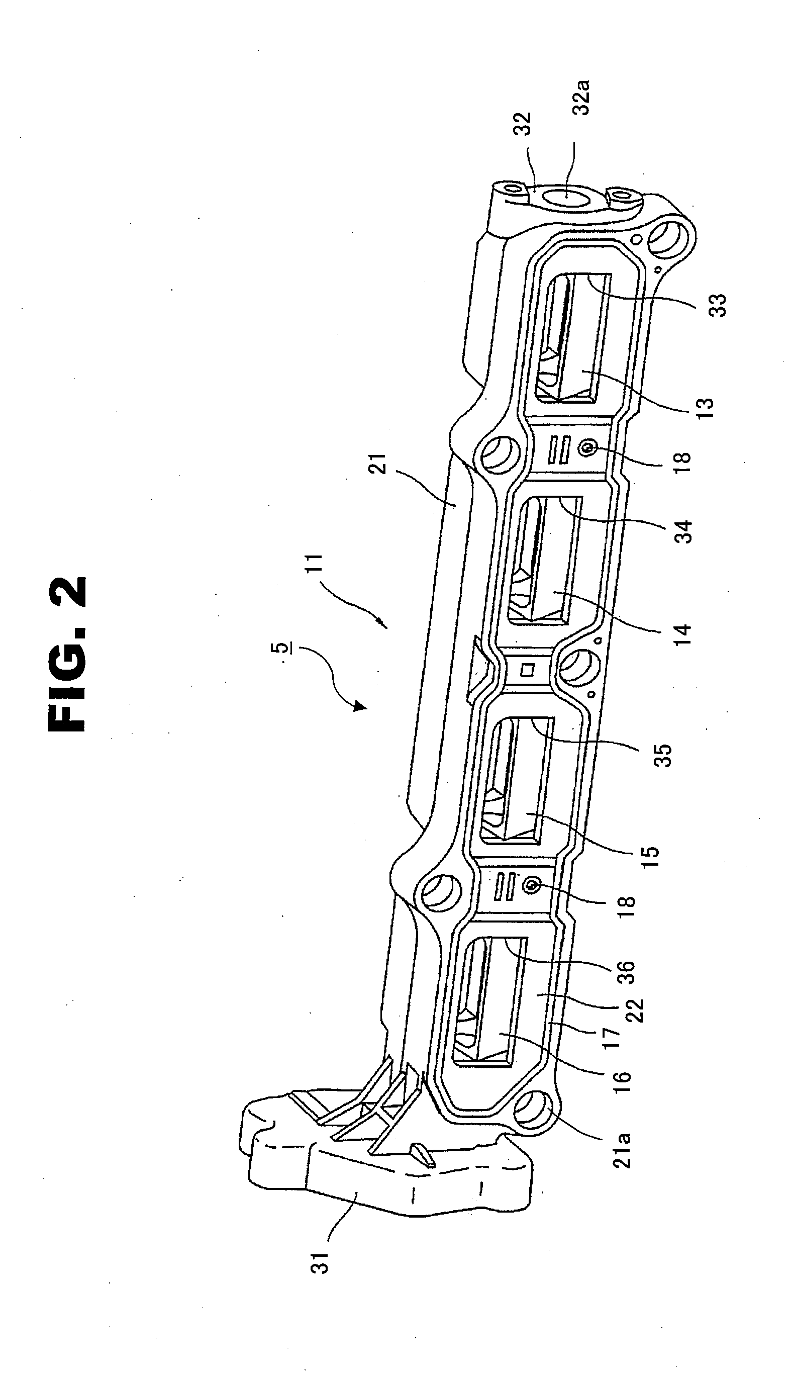
[0047]FIG. 2 is a perspective view of an intake control valve (the tumble control valve) 5 according to a first embodiment of the present invention. FIG. 3 is a perspective exploded view of the intake control valve (the tumble control valve) of the first embodiment.

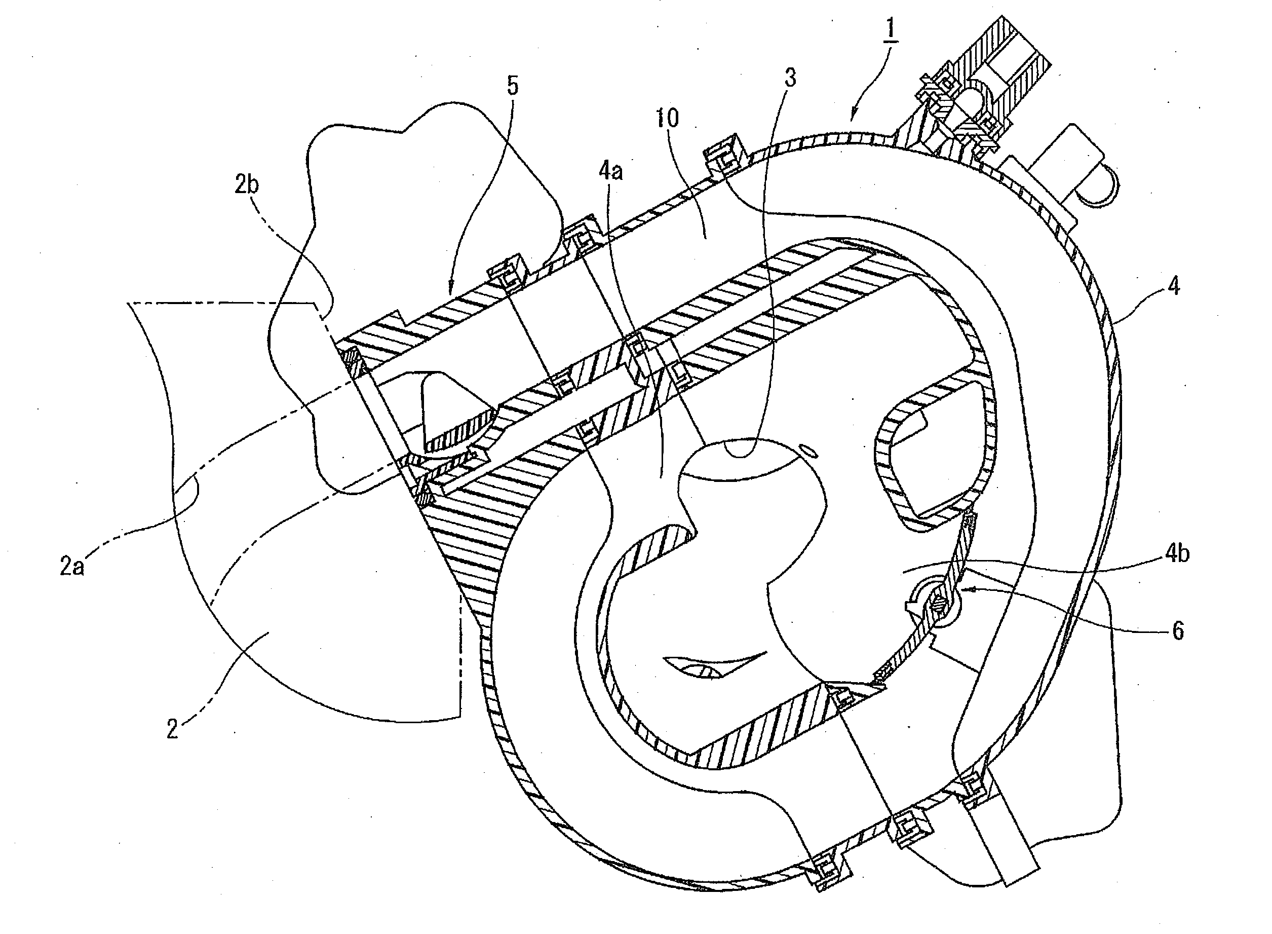
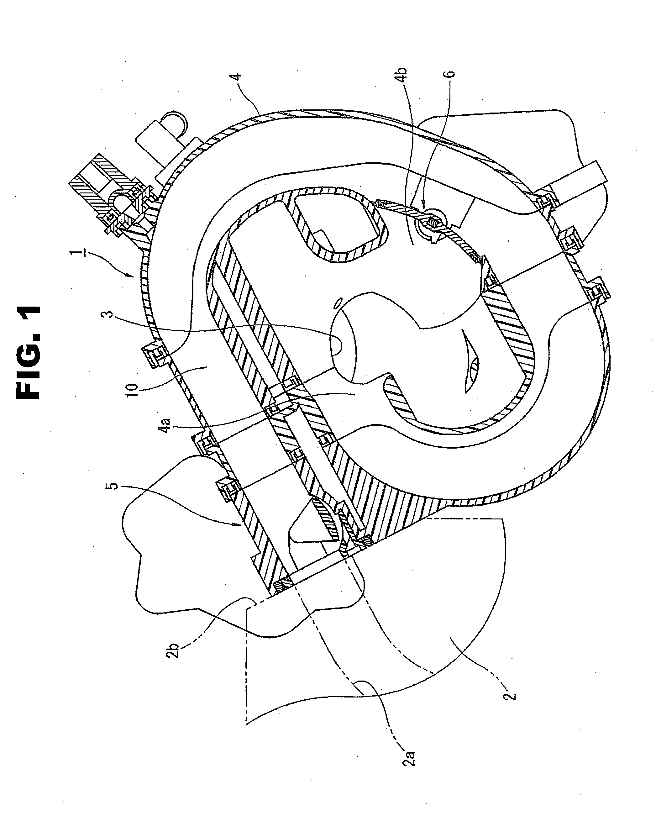
[0048]This tumble control valve 5 is formed mainly from a control valve housing (a housing) 11 that is fixed to a side surface (the mount surface 2b) of an intake side of the cylinder head 2 and a valve assembly 12 that has a series of four valve bodies 13 to 16.

[0049]The control valve housing 11 has a long narrow box-shaped housing body 21 that is formed, as an integral component, by hard synthetic resin material (rigid synthetic resin material) as a part of the intake manifold (a branch section is not shown), and a housing cover (a cover member) 22 that is formed by hard synthetic resin material (rigid synthetic resin material) and is fixed to the housing body 21 so as to cover a front surface of...

first modified example

[0082][First Modified Example]

[0083]FIG. 5 shows a first modified example of the present invention. Although a configuration of the tumble control valve 5 of this first modified example is almost the same as that of the tumble control valve 5 of the first embodiment, the protruding line 51 is provided not only at one end side along the rotation direction of the valve bodies 13 to 16, but also at the other end side along the rotation direction of the valve bodies 13 to 16. Each protruding line 51 is formed by the same hard synthetic resin material (the same rigid synthetic resin material) as that of the valve bodies 13 to 16, and is formed integrally with the respective valve bodies 13 to 16.

[0084]As shown in this first modified example, the protruding lines 51 could be provided in a plurality of positions on the valve bodies 13 to 16.

second modified example

[0085][Second Modified Example]

[0086]FIG. 6 shows a second modified example of the present invention. Although a configuration of the tumble control valve 5 of this second modified example is almost the same as that of the tumble control valve 5 of the first embodiment, the protruding line 51 is formed by different material from that of the valve bodies 13 to 16. That is, in this second modified example, the protruding line 51 is formed by rubber material or elastic material.

[0087]In the second modified example, a top edge of the protruding line 51 can touch the bottom surface of the valve accommodating recess 50, namely that the protruding line 51 moves along the arc-shaped bottom surface of the valve accommodating recess 50 with the top edge of the protruding line 51 coming into contact with the bottom surface of the valve accommodating recess 50. Thus, as compared with the first embodiment, an expelling performance of the deposits accumulated in the valve accommodating recess 50 ...


PUM


Abstract

An air intake system for an internal combustion engine has a valve body that can open/close a passage cross section of a part of an air intake passage; a rotation shaft that extends to both sides of the valve body and supports rotation of the valve body; a valve accommodating recess that is formed on an inner wall surface of the air intake passage and accommodates therein the valve body; and a protruding line that is formed on an outer peripheral side surface of the valve body, which faces the valve accommodating recess, and extends along a shaft direction of the rotation shaft. The air intake system further has a communication passage that directly connects the valve accommodating recess and an intake port of the internal combustion engine.

Description

BACKGROUND OF THE INVENTION[0001]The present invention relates to an air intake system for an internal combustion engine, which is provided at an upstream side of an intake port and generates gas flow (or gas stream) such as tumble flow in a combustion chamber of the internal combustion engine using a valve body by changing a cross section area of a part of an air intake passage.[0002]For instance, Japanese Patent Provisional Publications No. 2010-121551 (hereinafter is referred to as “JP2010-121551”) and No. 2010-242618 (hereinafter is referred to as “JP2010-242618”) each disclose an air intake system for the internal combustion engine, which is capable of changing an opening area of the air intake passage by a valve body whose rotation angle is changed from a fully open position in which a quantity of suction air flowing in the air intake passage becomes a maximum to a fully closed position in which the quantity of the suction air flowing in the air intake passage becomes a minimu...

Claims


Application Information

Patent Timeline
IPC IPC(8): F02M35/10
CPCF02M35/10118F02B31/06F02B2275/48F02D9/1015F02D9/1025F02D9/16F02D2041/0015F02M35/10065Y02T10/12F16K1/20F16K25/00
Inventor MATSUZAKI, JUNICHIKAWANO, TAKASHI
Owner MAHLE JAPAN LTD
Why Eureka
Try Eureka