Temperature Measuring Device for a Respiratory Humidifier

Active Publication Date: 2014-08-28
HAMILTON MEDICAL AG
View PDF2 Cites 4 Cited by
  • Summary
  • Abstract
  • Description
  • Claims
  • Application Information

AI Technical Summary

Benefits of technology

[0013]It is also advantageous for the surface of the flow guide element to have a structure. One possible structure is, for example, a set of holes; alternatively, the plate might be roughened or comprise a plurality of elevations or depressions, which can be of different shape, and so on. The structured surface serves to increase the turbulence of the breathing gas stream, so that it brings about the most homogeneous possible heating of the measurement portion. In addition, the turbulence of the breathing gas stream can also be helpful in increasing the uptake of moisture and heat by the breathing gas stream.
[0014]It is also advantageous for the measurement portion to b

Problems solved by technology

The disadvantage of this design of a temperature-measuring device is that it is not easy to manufacture a flow channel with a hollow body projecting into it, because either the hollow body must be formed out of the same material as the flow channel or perhaps bonded to it in a second production step, or alternati

Method used


Image

  • Temperature Measuring Device for a Respiratory Humidifier
  • Temperature Measuring Device for a Respiratory Humidifier
  • Temperature Measuring Device for a Respiratory Humidifier

Examples


Embodiment Construction

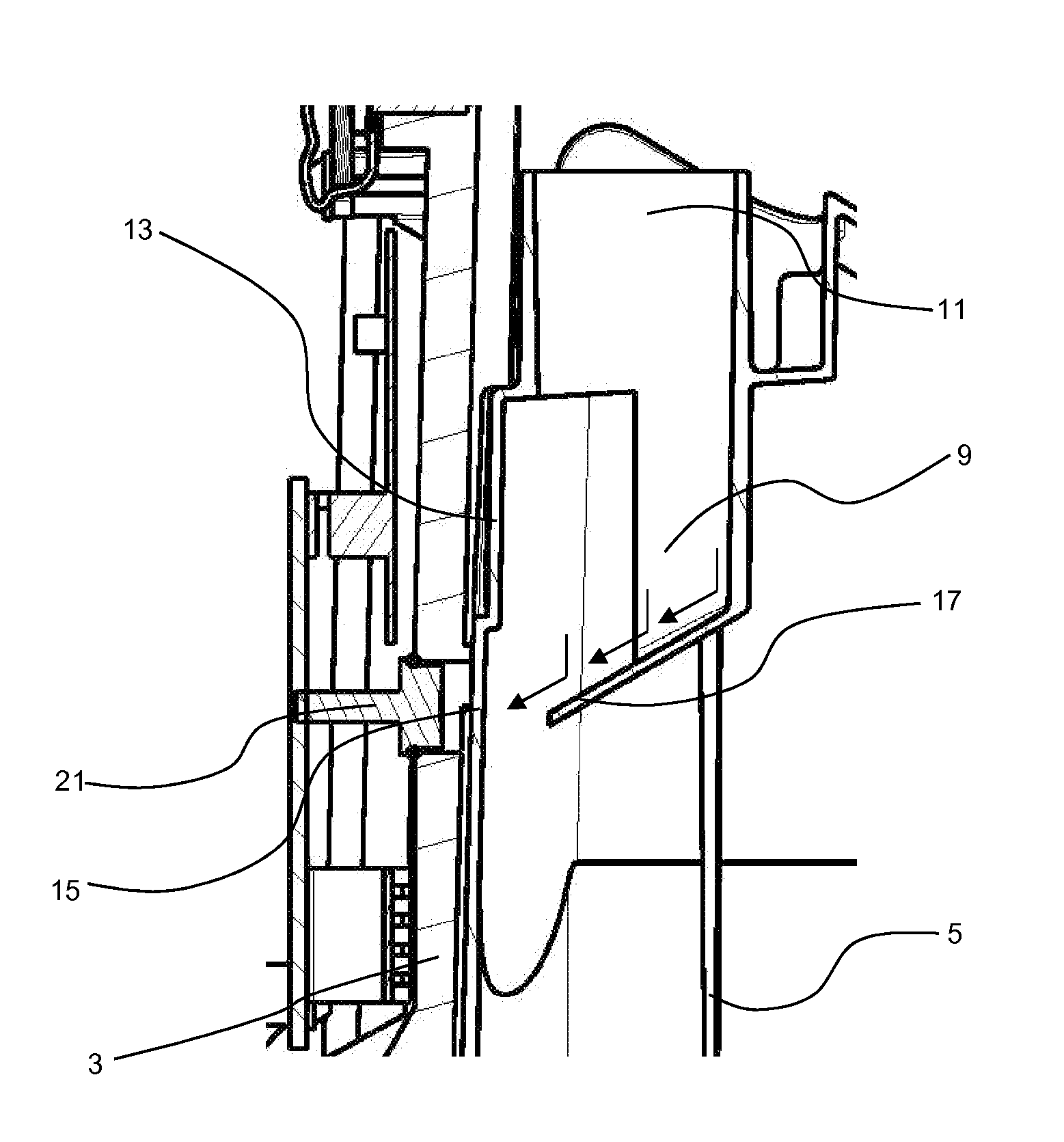
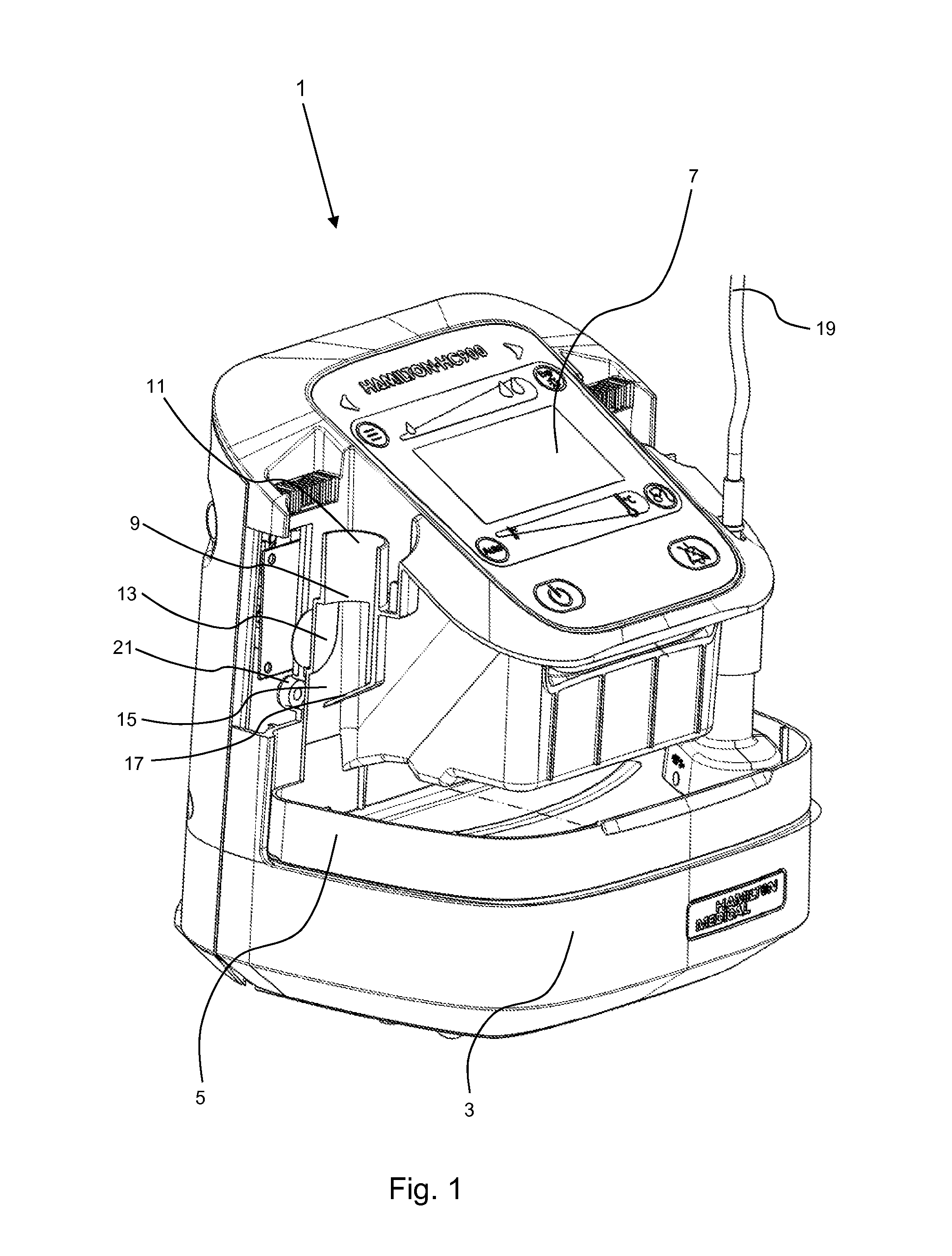
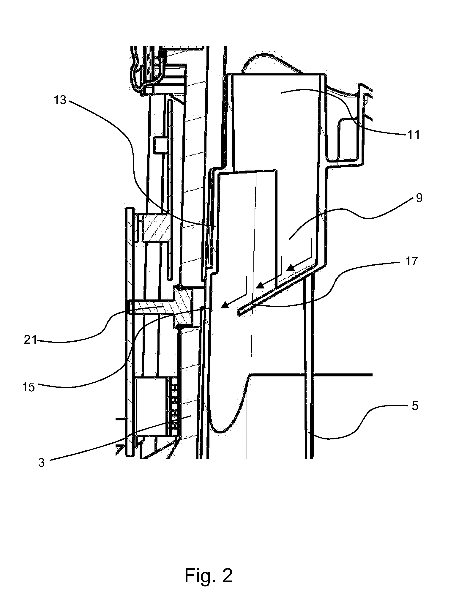
[0023]FIG. 1 shows a perspective view of a respiratory humidifier 1 with a housing 3 and a liquid container 5, inserted detachably into the housing 3, wherein parts of the housing 3 and of the liquid container 5 have been cut away to facilitate a better understanding of the invention. The liquid container 5 has an essentially U-shaped cross section in the horizontal direction, so that, after it has been inserted laterally / horizontally into the housing 3, it surrounds the central projecting section of the housing 3, on the top surface of which the user interface 7 with display and operating elements is arranged. In the area of the liquid container 5 shown on the left in FIG. 1, the container comprises a flow channel 9, which begins at a tubular socket 11 with a circular cross section and extends downward therefrom in the form of a lateral surface 13. The lateral surface 13, which is defined as the two-dimensional wall surface surrounding the flow channel 9, comprises a measurement po...


PUM


Abstract

A temperature-measuring device for a respiratory humidifier (1) with a liquid container (5) is provided, wherein the temperature-measuring device comprises a flow channel (9) for breathing gas and an infrared detector (21), which is directed from the outside toward the flow channel (9) for the contactless detection of the temperature of the breathing gas in the flow channel (9), wherein the flow channel (9) comprises on its lateral surface (13) a measurement portion (15), which is aligned with the surrounding areas of the lateral surface (13) and toward which the infrared detector (21) is directed, wherein the flow channel (9) comprises a flow guide element (17), which conducts the breathing gas stream to the measurement portion (15) at a previously determined inflow angle of preferably greater than 10° and less than 170°.

Description

FIELD OF INVENTION[0001]The present invention pertains to a temperature-measuring device for a respiratory humidifier for ventilating patients with breathing gas.BACKGROUND OF THE INVENTION[0002]When patients are being mechanically ventilated on an intensive-care ward, for example, the patient to be ventilated is connected pneumatically to the respirator by a system of ventilation tubing. Because the breathing gas supplied to the patient must be adjusted with respect to temperature and humidity to meet the physiological needs of the patient, a respiratory humidifier is arranged in the inhalation or inspiration tube to heat and humidify the breathing gas. The respiratory humidifier usually comprises a liquid container filled with distilled water, the bottom plate of the container being in thermal contact with a heating plate in the housing, as a result of which the liquid is warmed. The inhalation gas is conducted into the liquid container, is thus humidified, and then leaves the liq...

Claims


Application Information

Patent Timeline
IPC IPC(8): A61M16/16
CPCA61M16/16A61M2205/3313A61M2205/3368A61M16/109A61M2205/3306G01J5/0014G01J5/025G01J5/0806G01J5/0893
Inventor BUECHI, RUDOLF
Owner HAMILTON MEDICAL AG
Why Eureka
Try Eureka